Ozone removal device, image forming apparatus having the same, and method for removing ozone

a technology which is applied in the field of ozone removal device and image forming apparatus having the same, can solve the problems of troublesome replacement of filters, increased electricity consumption, and increased difficulty in adjusting the filter, so as to save user's trouble, reduce the concentration of ozone, and reduce the effect of electricity consumption

Inactive Publication Date: 2008-09-11
SHARP KK
View PDF19 Cites 25 Cited by
  • Summary
  • Abstract
  • Description
  • Claims
  • Application Information

AI Technical Summary

Benefits of technology

[0012]As a result of a keen examination on a method for removing ozone, the inventors of the present invention found that the negative ions emitted into an atmosphere have an ozone reduction effect although the mechanism of this action is unclear. According to the arrangement, the ion emitting section emits the negative ions into an atmosphere and thereby an ozone concentration is reduced. Thus, ozone removal can be carried out.
[0013]According to the arrangement, there is no need to use an ozone decomposing filter for ozone removal. Therefore, this arrangement makes it possible to save user's trouble because the replacement of the filter is not required. This arrangement also makes it possible to hold electricity consumption down because a large amount of electricity is not required for heat decomposition.

Problems solved by technology

However, the conventional ozone removal techniques have the problems below.
Accordingly, this entails an expenditure of required periodic replacement of the filter.
Besides, the replacement of the filter is troublesome because a user needs to dismount a device or call a serviceperson.
A cost burden of electricity consumption is heavy because such a temperature raise requires a large amount of electricity.

Method used


Image

  • Ozone removal device, image forming apparatus having the same, and method for removing ozone
  • Ozone removal device, image forming apparatus having the same, and method for removing ozone
  • Ozone removal device, image forming apparatus having the same, and method for removing ozone

Examples


embodiment 1

[0026]An embodiment of the present invention is described below with reference to FIGS. 1 to 5. The present embodiment describes a case where the ozone removal device of the present invention is applied to a color laser printer, which is an image forming apparatus.

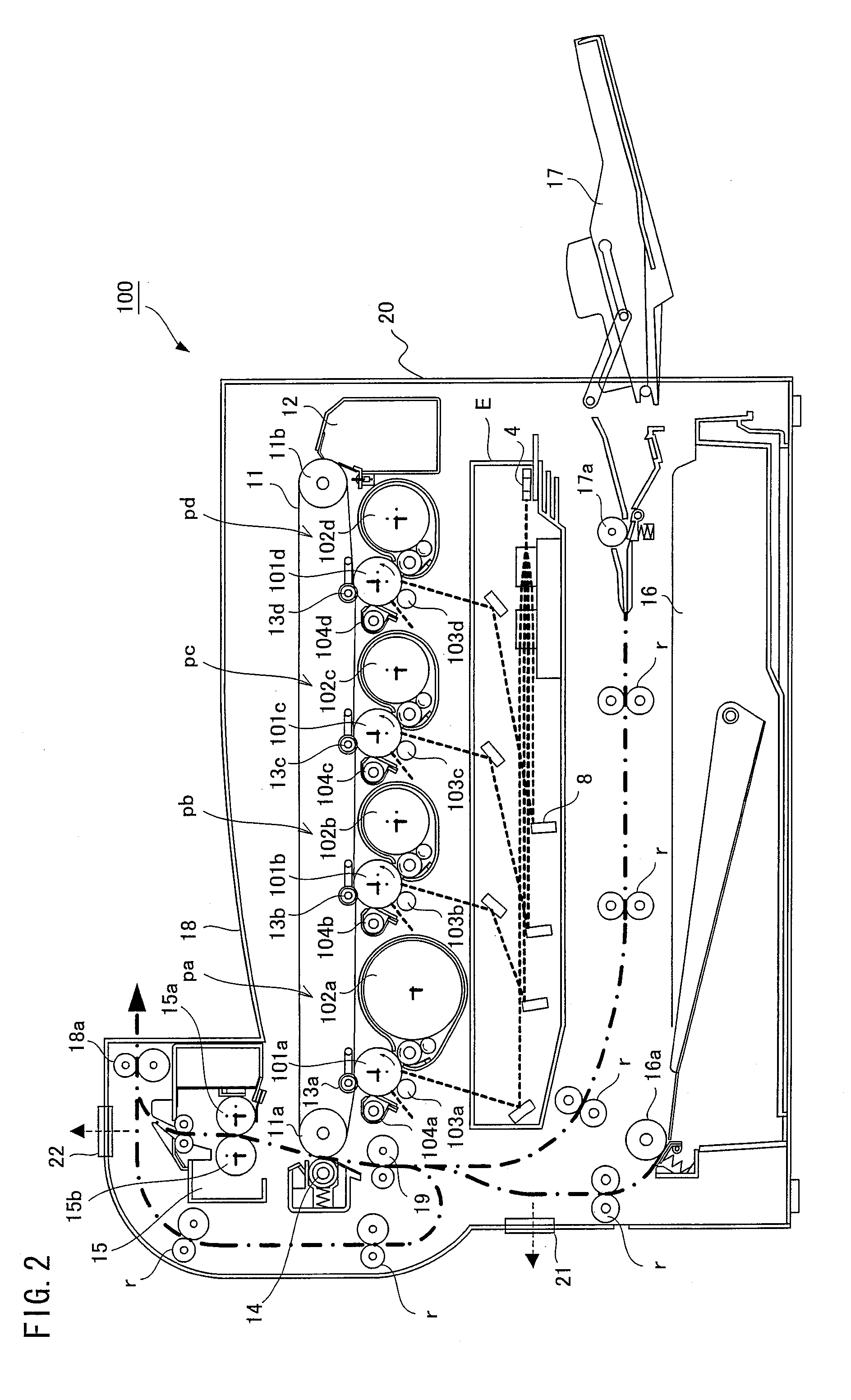
[0027]FIG. 2 is a longitudinal sectional view illustrating a schematic structure of a color laser printer (image forming apparatus) 100 in accordance with one embodiment of the present invention. As illustrated in FIG. 2, the color laser printer 100 of the present embodiment includes an optical system unit E, four visible image forming units pa, pb, pc, and pd, an intermediate transfer belt 11, a secondary transferring unit 14, a fixing unit 15, an internal paper feeding unit 16, a manual paper feeding unit 17, and a housing 20 containing these members.

[0028]The visible image forming unit pa includes a photoreceptor 101a, a charging unit 103a, a developing unit 102a, a cleaning unit 104a, and a primary transferring unit 13...

embodiment 2

[0054]Another embodiment of the present invention is described below with reference to FIGS. 8 and 9. For convenience of explanation, members with the same functions as those of members of Embodiment 1 are given the same reference numerals and explanations thereof are omitted. In the present embodiment, too, an explanation will be made as to a case where the ozone removal device of the present invention is applied to a color laser printer which is an image forming apparatus.

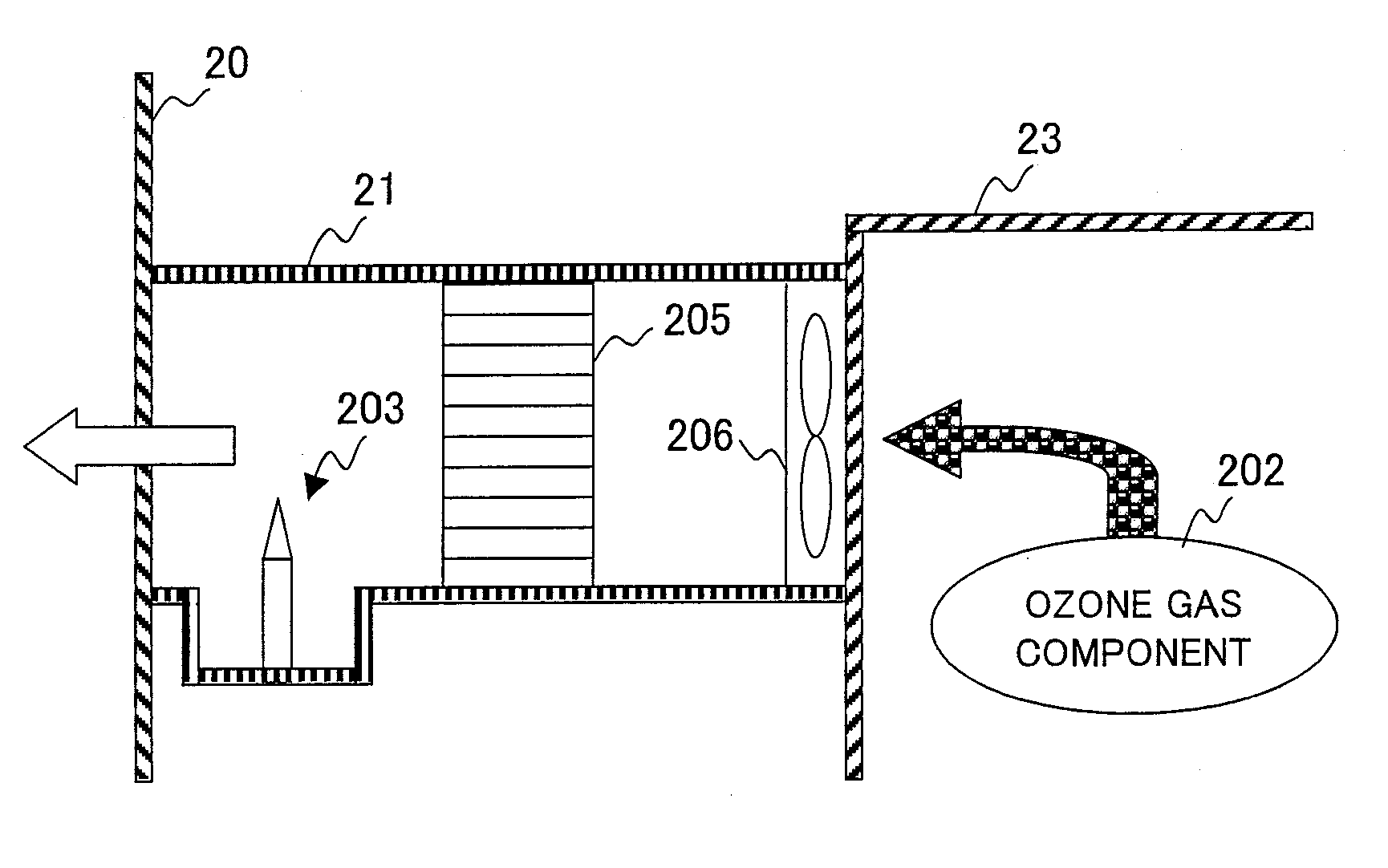
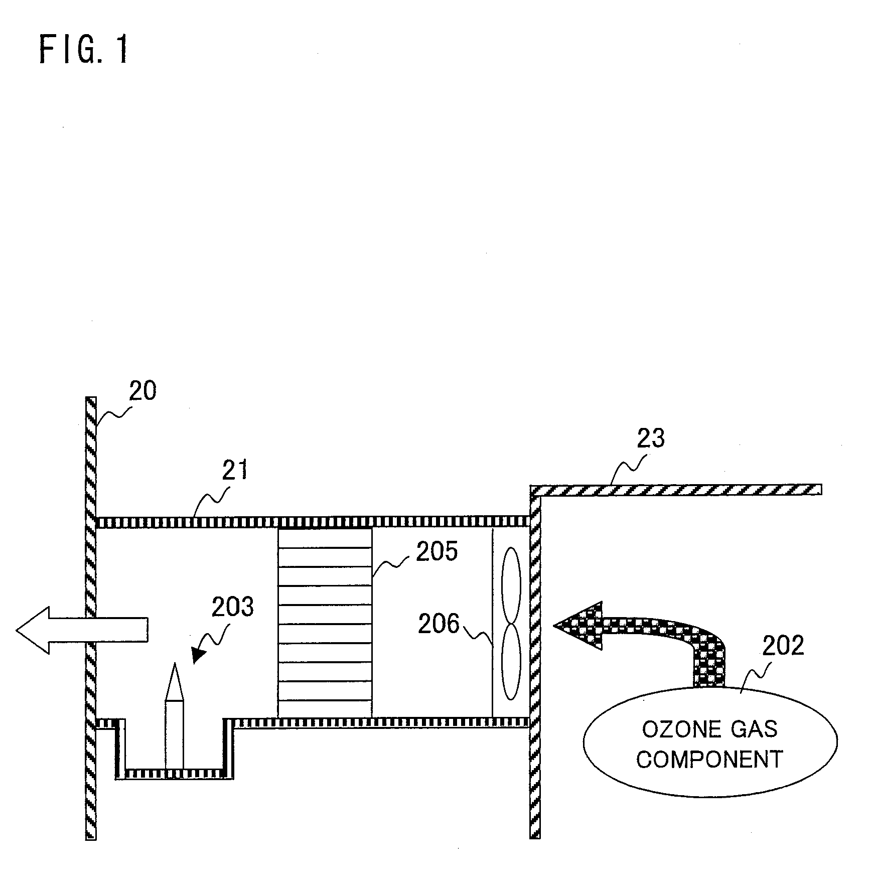
[0055]As illustrated in FIG. 9, a color laser printer 100′ of the present embodiment is basically the same as the color laser printer of Embodiment 1 except that the color laser printer 100′ includes a first exhaust duct 21′ instead of the first exhaust duct 21. What is different between the first exhaust duct 21′ and the first exhaust duct 21 is that, inside the first exhaust duct 21′, as illustrated in FIG. 8, an electric field forming unit (electric field forming section) 207 is provided in order to generate a...

example 1

[0060]An ozone decomposition effect by the ion emitting unit 203 was verified through the experiment below with the color laser printer 100 of Embodiment 1.


PUM


Abstract

A color laser printer is provided with a first exhaust duct for exhausting ozone generated by a charging unit etc. inside a housing to the outside of the housing. The first exhaust duct is therein provided with a catalytic honeycomb filter for ozone gas treatment and an ion emitting unit for emitting negative ions into an atmosphere. Most of an ozone gas component is decomposed and/or absorbed by the catalytic honeycomb filter for ozone gas treatment. Furthermore, the residual ozone gas component is decomposed by the negative ions generated by the ion emitting unit. This arrangement makes it possible to provide a new ozone removal device which is different from an ozone decomposing filter or a heat source.

Description

[0001]This Nonprovisional application claims priority under 35 U.S.C. § 119(a) on Patent Application No. 057869 / 2007 filed in Japan on Mar. 7, 2007 and Patent Application No. 284536 / 2007 filed in Japan on Oct. 31, 2007, the entire tents of which are hereby incorporated by reference.FIELD OF THE INVENTION[0002]This invention relates to an ozone removal device for removing ozone in an atmosphere, a method for removing ozone, and an image forming apparatus including the ozone removal device.BACKGROUND OF THE INVENTION[0003]A process for charging an image carrier such as a photosensitive drum and a process for transferring a toner image on the image carrier to a recording paper or an intermediate transfer belt are absolutely required for an image forming apparatus based on the electrophotographic process. A charger and a transferor of a contact-type which are roller-shaped or brush-shaped can be employed for the processes. Due to contact with the image carrier and the intermediate trans...

Claims


Application Information

Patent Timeline
Patent Type & Authority Applications(United States)
IPC IPC(8): G03G21/20G21G5/00
CPCG03G21/206
Inventor DOSHOHDA, HIROSHIADACHI, KATSUMIKAGAWA, TOSHIAKI
Owner SHARP KK
Why Eureka
Try Eureka