Efficient treatment equipment for industrial ozone-containing waste gas

A kind of treatment equipment and high-efficiency technology, applied in the separation of dispersed particles, chemical instruments and methods, filtration of dispersed particles, etc., can solve the problems of insufficient exhaust gas treatment, low ozone removal rate, human health hazards, etc., to save energy consumption, The effect of ensuring filter quality and prolonging service life

Inactive Publication Date: 2019-11-22
XUZHOU TIANLAN OZONE EQUIP CO LTD
View PDF0 Cites 3 Cited by
  • Summary
  • Abstract
  • Description
  • Claims
  • Application Information

AI Technical Summary

Problems solved by technology

Although a small amount of ozone can play a role in disinfection and sterilization, it can also be used in industry to treat waste water containing polycyclic aromatic hydrocarbons and unsaturated hydrocarbons such as polychlorinated biphenyls, phenol, naphthalene, etc. Chemical reactivity, strong irritant, harmful to human health
[0003] When the existing ozone-containing waste gas is treated, the ozone removal rate in the waste gas is relatively low, the treatment of the waste gas is not thorough enough, and it is discharged into the atmosphere to pollute the environment. The dilution method, washing method, thermal decomposition method, and adsorption method are used alone. method, catalytic decomposition method, etc. are slightly insufficient, and cannot be effectively combined. Therefore, we propose a high-efficiency treatment equipment for industrial ozone-containing waste gas

Method used


Image

  • Efficient treatment equipment for industrial ozone-containing waste gas
  • Efficient treatment equipment for industrial ozone-containing waste gas
  • Efficient treatment equipment for industrial ozone-containing waste gas

Examples


Embodiment

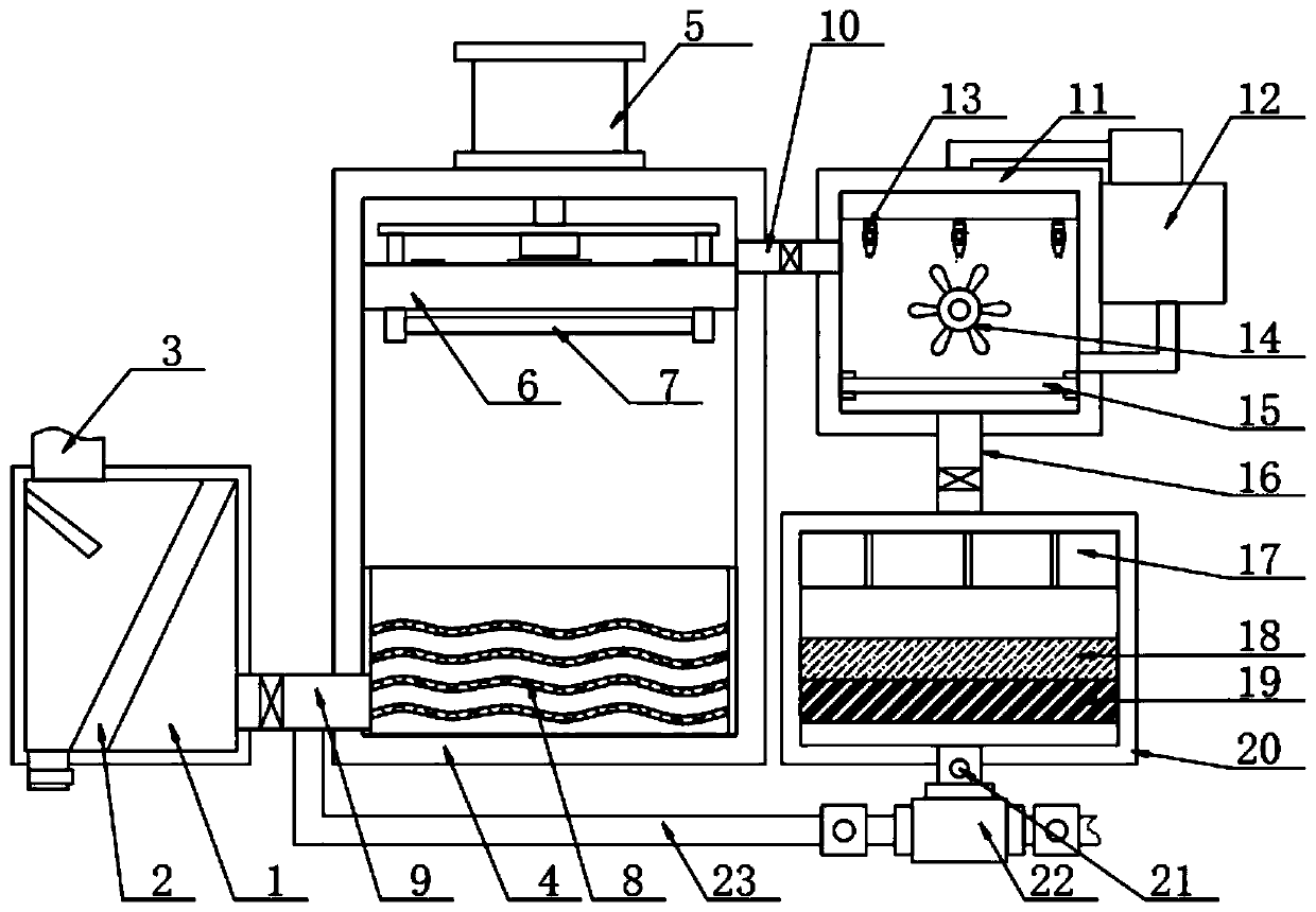
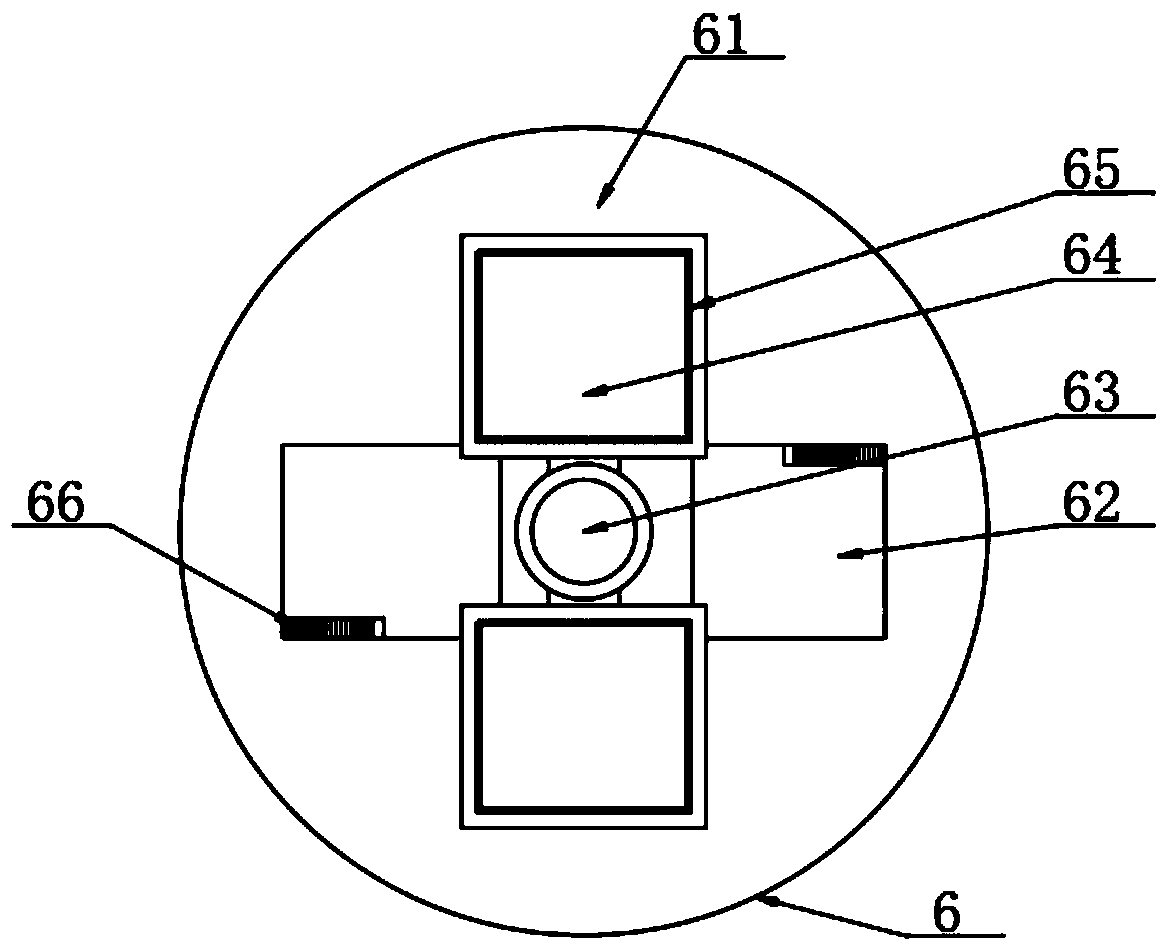
[0044]Embodiment: connect the connection inlet pipe 3 with the equipment for external input of exhaust gas, the exhaust gas enters the preliminary purification shell 1 through the connection inlet pipe 3, filters the solid particles in the exhaust gas through the filter plate 2, and then enters the decomposition through the connecting pipe 9 Inside the casing 4 and below the heating piston 6, start the high-temperature heating tube 7 and the cylinder 5, the cylinder 5 drives the heating piston 6 downward, presses the exhaust gas downward, the high-temperature heating tube 7 heats the exhaust gas at high temperature, and the heat storage plate 8 Heat absorption, exhaust gas heating, removal of a certain concentration of ozone in the exhaust gas, after heating for a certain period of time, start the micro motor 63 to rotate clockwise, so that the sealing baffle 64 does not block the port 62, and the heated gas passes through the port 62 It flows upwards, then enters the spray hou...


PUM


Abstract

The invention discloses efficient treatment equipment for industrial ozone-containing waste gas, and belongs to the technical field of waste gas treatment. The equipment includes an initial purification shell, wherein a decomposition shell is arranged on the right side of the primary purification shell; a drying part is arranged at the top of an inner cavity of the efficient purification shell; the other end of the communicating pipe III penetrates through the top of the efficient purification shell and is connected with the top of the drying part; a catalyst layer I and a catalyst layer II are sequentially arranged at the bottom of an inner cavity of the efficient purification shell from top to bottom. The method comprises the following steps: firstly, performing initial treatment on thewaste gas entering the system by means of the filter plate, so that solid particles in the waste gas are removed, the pipeline blockage caused by subsequent waste gas flowing is further avoided, and purification load in the following steps is reduced; meanwhile, the design that the guide plate and the filter plate are inclined is adopted, so that waste gas entering the connecting air inlet pipe gives certain impact force to the filter plate, solid particles remaining on the filter plate can be better discharged through the blow-off pipe, the service life of the filter plate is prolonged, and the long-term effective filter quality of the filter plate is guaranteed.

Description

technical field [0001] The invention relates to the technical field of waste gas treatment, in particular to a high-efficiency treatment equipment for industrial ozone-containing waste gas. Background technique [0002] Ozone is an allotrope of oxygen, a light blue gas with a strong pungent odor. Although a small amount of ozone can play a role in disinfection and sterilization, it can also be used in industry to treat waste water containing polycyclic aromatic hydrocarbons and unsaturated hydrocarbons such as polychlorinated biphenyls, phenol, naphthalene, etc. The chemical reactivity of the chemical has a strong irritant and is harmful to human health. [0003] When the existing ozone-containing waste gas is treated, the ozone removal rate in the waste gas is relatively low, the treatment of the waste gas is not thorough enough, and it is discharged into the atmosphere to pollute the environment. The dilution method, washing method, thermal decomposition method, and adsor...

Claims


Application Information

Patent Timeline
Patent Type & Authority Applications(China)
IPC IPC(8): B01D53/74B01D53/75B01D53/86B01D53/66B01D46/10
CPCB01D46/10B01D53/74B01D53/75B01D53/8675B01D53/869
Inventor 孙锋
Owner XUZHOU TIANLAN OZONE EQUIP CO LTD
Why Eureka
Try Eureka