Apparatus and method of heating image on recordable material

Active Publication Date: 2008-09-11
HEWLETT PACKARD DEV CO LP
View PDF10 Cites 10 Cited by
  • Summary
  • Abstract
  • Description
  • Claims
  • Application Information

AI Technical Summary

Benefits of technology

[0016]The present general inventive concept provides an image heating apparatus which can adjust a de

Problems solved by technology

Therefore, the conventional method and apparatus cannot reduce a

Method used


Image

  • Apparatus and method of heating image on recordable material
  • Apparatus and method of heating image on recordable material
  • Apparatus and method of heating image on recordable material

Examples


Embodiment Construction

[0050]Reference will now be made in detail to the embodiments of the present general inventive concept, examples of which are illustrated in the accompanying drawings, wherein like reference numerals refer to the like elements throughout. The embodiments are described below in order to explain the present general inventive concept by referring to the figures.

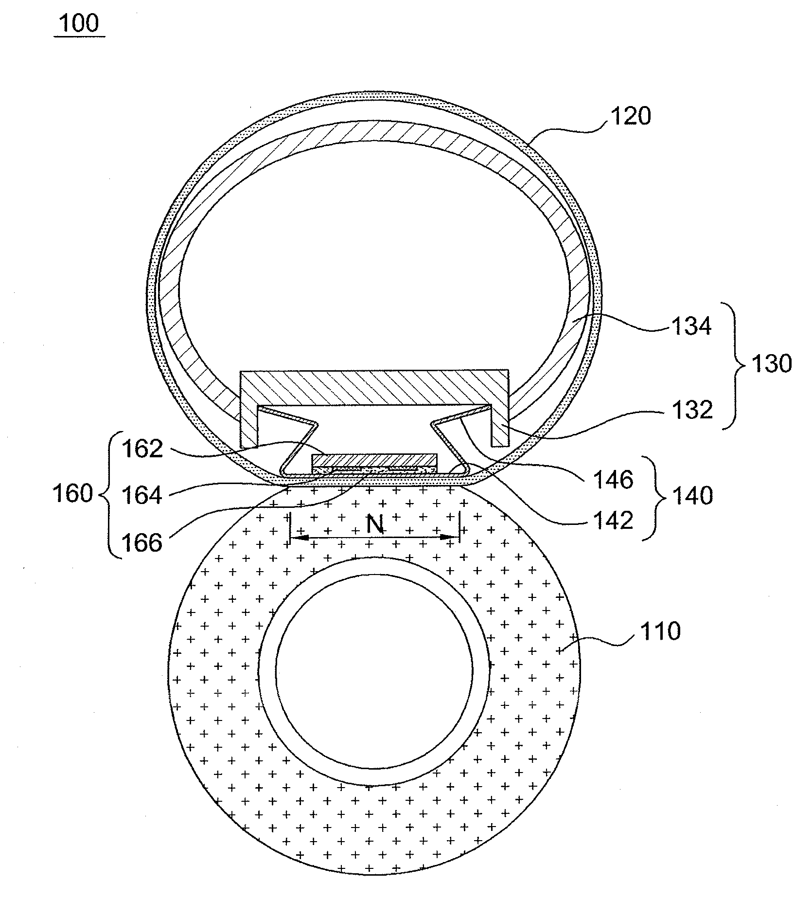
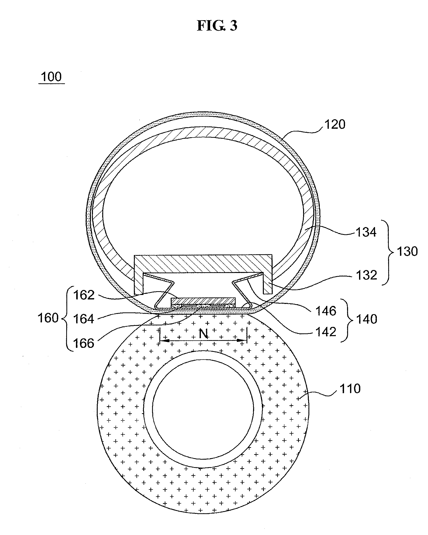
[0051]FIG. 3 is a cross-sectional view illustrating an image heating apparatus 100 according to an embodiment of the present general inventive concept, and FIG. 4 is an exploded perspective view illustrating the image heating apparatus 100 of FIG. 3.

[0052]The image heating apparatus 100 may be installed in an apparatus including a printing function, such as a copying machine, a printer, a facsimile, and the like. Also, the image heating apparatus 100 may fuse a toner image on a printing paper or other recording medium. A specific installation location and the like may be known by referring to descriptions related to the image he...


PUM


Abstract

An image heating apparatus includes a pressure roller, a belting film to circulate while partially connecting with the pressure roller, a support member to be provided in the belting film and comprises a guide to guide the circulating of the belting film, a nip spring to comprise a nip portion to form a nip between the belting film and the pressure roller, and a support portion to support the nip portion against the support member, and a heater to be provided adjacent to the nip spring and transfer heat to the image through the belting film.

Description

CROSS-REFERENCE TO RELATED APPLICATIONS[0001]This application claims priority under 35 U.S.C §119(a) from Korean Patent Application No. 10-2007-0021860, filed on Mar. 6, 2007, in the Korean Intellectual Property Office, the disclosure of which is incorporated herein in its entity by reference.BACKGROUND OF THE INVENTION[0002]1. Field of the Invention[0003]The present general inventive concept relates to an image heating apparatus, and more particularly, to a method and apparatus to fuse an image, which can reduce a warm-up time and also can improve a fusing quality.[0004]2. Description of the Related Art[0005]An image heating apparatus generally includes a heating roller and a pressure roller. The image heating apparatus may pass a printing paper, formed with an image, through the heating roller and the pressure roller and thereby fuse the image on the printing paper. Accordingly, the image heating apparatus may be used for a copying machine, a printer, a facsimile, and the like. Al...

Claims


Application Information

Patent Timeline
IPC IPC(8): G03G15/20
CPCG03G2215/2035G03G15/2064G03G15/2053
Inventor LEESHIN, SO HOKIM, HWAN GUEMKIM, TAE GYU
Owner HEWLETT PACKARD DEV CO LP
Why Eureka
Try Eureka