Intrusion-inhibiting building closure

Inactive Publication Date: 2008-09-18
SALZER SICHERHEITSTECHN
View PDF8 Cites 8 Cited by
  • Summary
  • Abstract
  • Description
  • Claims
  • Application Information

AI Technical Summary

Benefits of technology

[0017]One embodiment of the present invention makes provision for the fastener to be connected to a reinforcing profiled section arranged on the inside of the inner frame section, with the reinforcing profiled section being developed for example as a hollow profiled section. Such a reinforcing profiled section, which in contrast to the frame sections should be made of steel, is arranged within the inner frame section in order to increase the stability of the building closure and the connection between the frame sections.
[0021]A refinement of the invention makes provision for the protective strips to be connected by means of at least one fastener to a profiled section located in a space bordered on the one hand by the end of the filling and on the other by the planes of the inner and outer sides of the filling, in particular an additional reinforcing insert arranged there. This increases the stability of the connection considerably on the one hand, while the additional coupling increases the barrier to intrusion on the other.
[0023]It is advantageous when the coupling element and / or the reinforcing inserts are located in an area between a first plane, defined by the outer side of the filling, and a second plane, defined by the inner side of the filling.
[0024]Finally, it is advantageous when the bolt fastening the protective strips extends through two walls of the rear chamber of the outer frame section and the coupling element arranged between them in the form of a web and is ultimately screwed together with a reinforcing insert in the form of a flat profiled section, with the reinforcing insert running parallel to the web and outside the chamber of the outer frame section.
[0029]It is particularly advantageous if the locking pin or bolt creates a form-fitting connection between the bolt and the protective strips, also in a section of plain shank adjacent to the head. In this manner, relative movement between the remaining shaft of the bolt and the protective strips is prevented even in the event that the head of the bolt has been successfully drilled away.
[0030]Furthermore, provision is made in accordance with the present invention for the bolt to have a countersunk head that does not project above the outer side of the protective strips and for the locking pin or bolt to run at an angle in relation to the outer side of the protective strips that corresponds to the angle of inclination of a tapered countersink of a through hole in the protective strips for the countersunk bolt and also for the locking pin not to protrude beyond the outer side of the protective strips. As a result, this serves to prevent relative movement between the fastener and the protective strips as well as to prevent the removal of the locking pin.

Problems solved by technology

This means that an unauthorized person is not in a position to access the fastener from the outside of the building closure or to destroy or move it in such a way that the connection with the structural member would be removed and it would be possible to access the inside of the building after removing the protective strip and taking further steps involving dismantling.
If the end of the fastener to be manipulated is located in the area of the glazing rebate, manipulation is impossible when the filling is installed because this area is covered.

Method used


Image

  • Intrusion-inhibiting building closure
  • Intrusion-inhibiting building closure
  • Intrusion-inhibiting building closure

Examples


Embodiment Construction

[0048]Throughout all the Figures, same or corresponding elements are generally indicated by same reference numerals. These depicted embodiments are to be understood as illustrative of the invention and not as limiting in any way. It should also be understood that the drawings are not necessarily to scale and that the embodiments are sometimes illustrated by graphic symbols, phantom lines, diagrammatic representations and fragmentary views. In certain instances, details which are not necessary for an understanding of the present invention or which render other details difficult to perceive may have been omitted.

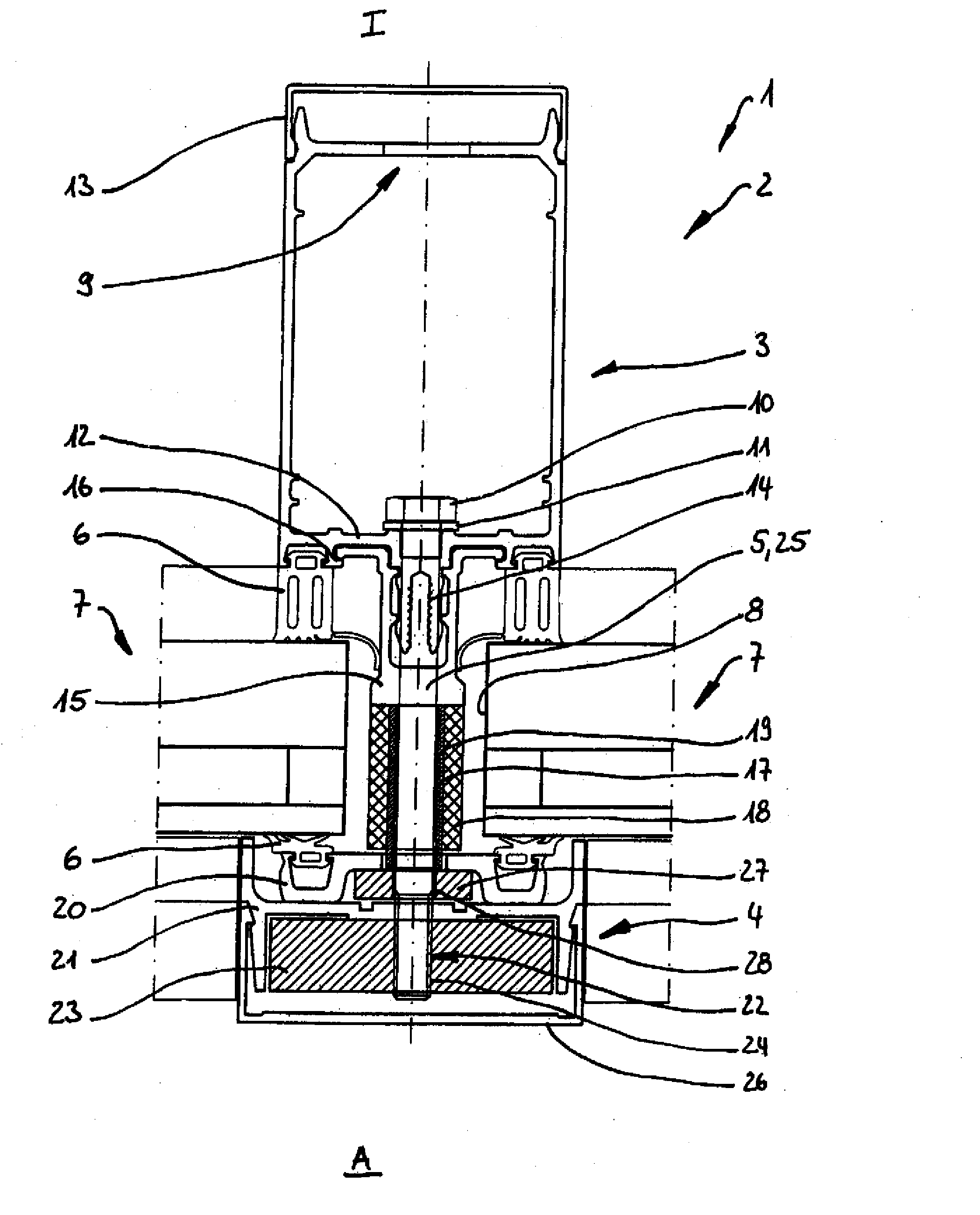
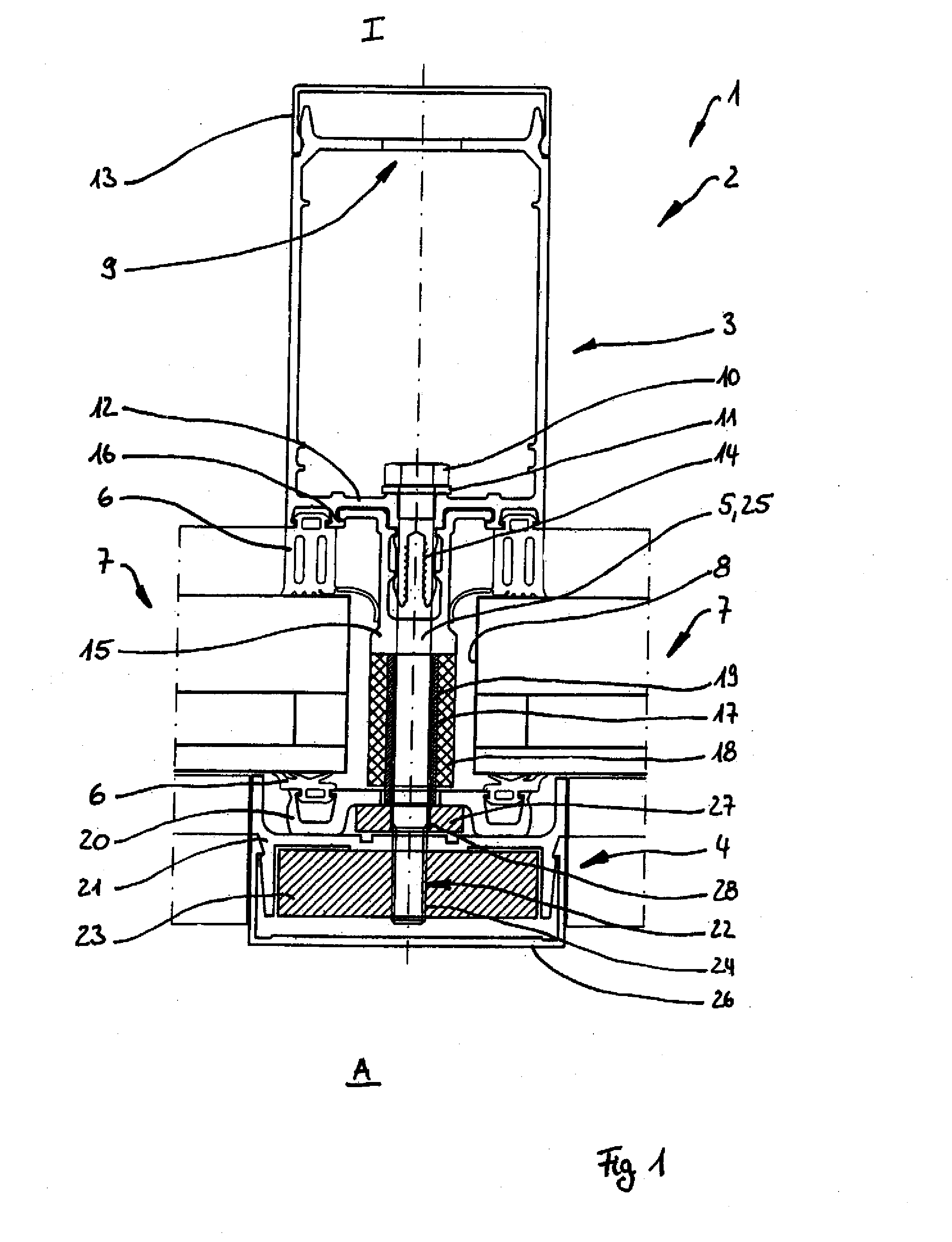
[0049]Turning now to the drawing, and in particular to FIG. 1, there is shown a horizontal cross-section through a building closure 1 in accordance with the invention, indicating the structure of the frame elements 2. The aluminum frame elements 2 consist of one inner frame section 3 and one outer frame section 4 running parallel to it, which are connected to each other by mea...


PUM


Abstract

An intrusion-inhibiting building closure is disclosed having a frame structure consisting of frame elements and at least one filling fully enclosed by frame elements at its front ends, with each frame element comprising one inner frame section and one outer frame section connected to it by a connecting element, with each outer frame section being provided with an intrusion-inhibiting protective strip made from a material that is resistant to abrasion, breakage and deformation or the outer frame sections themselves consist of a material that is resistant to abrasion, breakage and deformation and an intrusion-inhibiting protective strip with each protective strip connected to the corresponding frame element by means of at least one fastener arranged in a manner that makes them inaccessible from the outside of the building closure provided with protective strips and to be connected to a reinforcing profiled section running inside or outside the corresponding frame section and parallel to it and / or to the inner frame section.

Description

CROSS REFERENCE TO RELATED APPLICATIONS[0001]This application claims the benefit of priority under 35 U.S.C §119 of German Utility Model 20 2007 007 554.5 filed on May 25, 2007 and of German Utility Model 20 2007 004 060.1 filed on Mar. 15, 2007, the disclosures of which are incorporated herein by reference.BACKGROUND OF THE INVENTION[0002]The invention relates to an intrusion-inhibiting building closure, and in particular building closure having a frame structure consisting of frame elements and at least one filling fully enclosed by frame elements along its periphery at its front ends.State of the Art [0003]Within the scope of the present application, a building closure is a flat closing element that is developed to be openable or firmly closed and can be provided with a transparent or non-transparent filling. Building closures of this kind are generally known as so-called “pillar and beam facades”, the vertical frame elements (“pillars”) and horizontal frame elements (“beams”) of...

Claims


Application Information

Patent Timeline
IPC IPC(8): E06B3/26
CPCE06B5/116E04B2/96
Inventor SALZER, HEINRICH
Owner SALZER SICHERHEITSTECHN
Why Eureka
Try Eureka