
Multifunctional operating element
- Summary
- Abstract
- Description
- Claims
- Application Information
AI Technical Summary
Benefits of technology
Problems solved by technology
Method used
Image

Examples
Embodiment Construction
[0023]In the following description, position references refer to the representation in the figures. In the installed state, the operating element can have any desired position, in which these position references would then no longer apply.
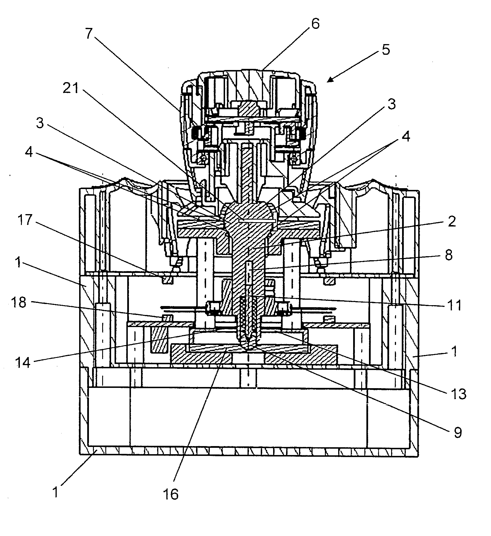
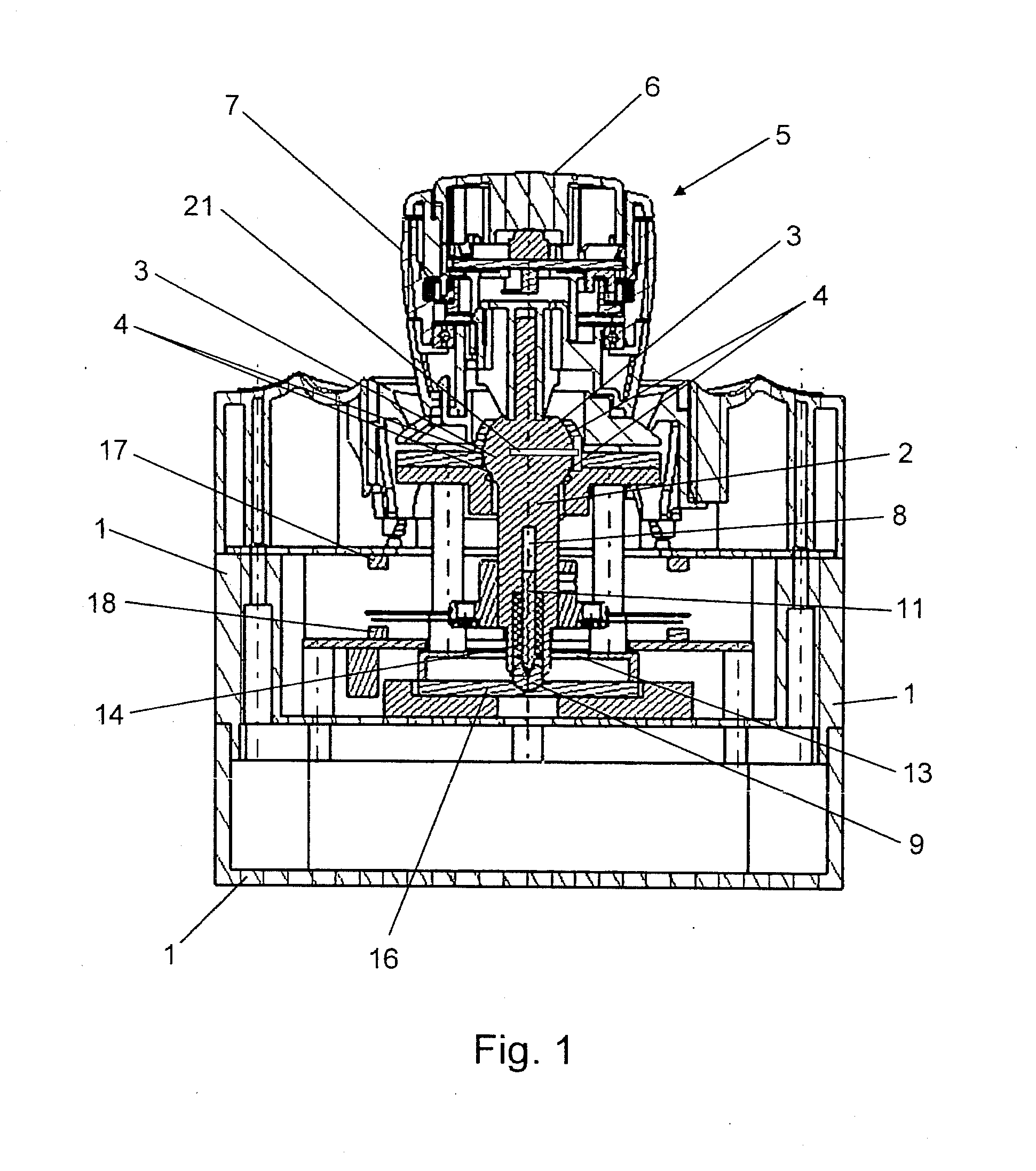
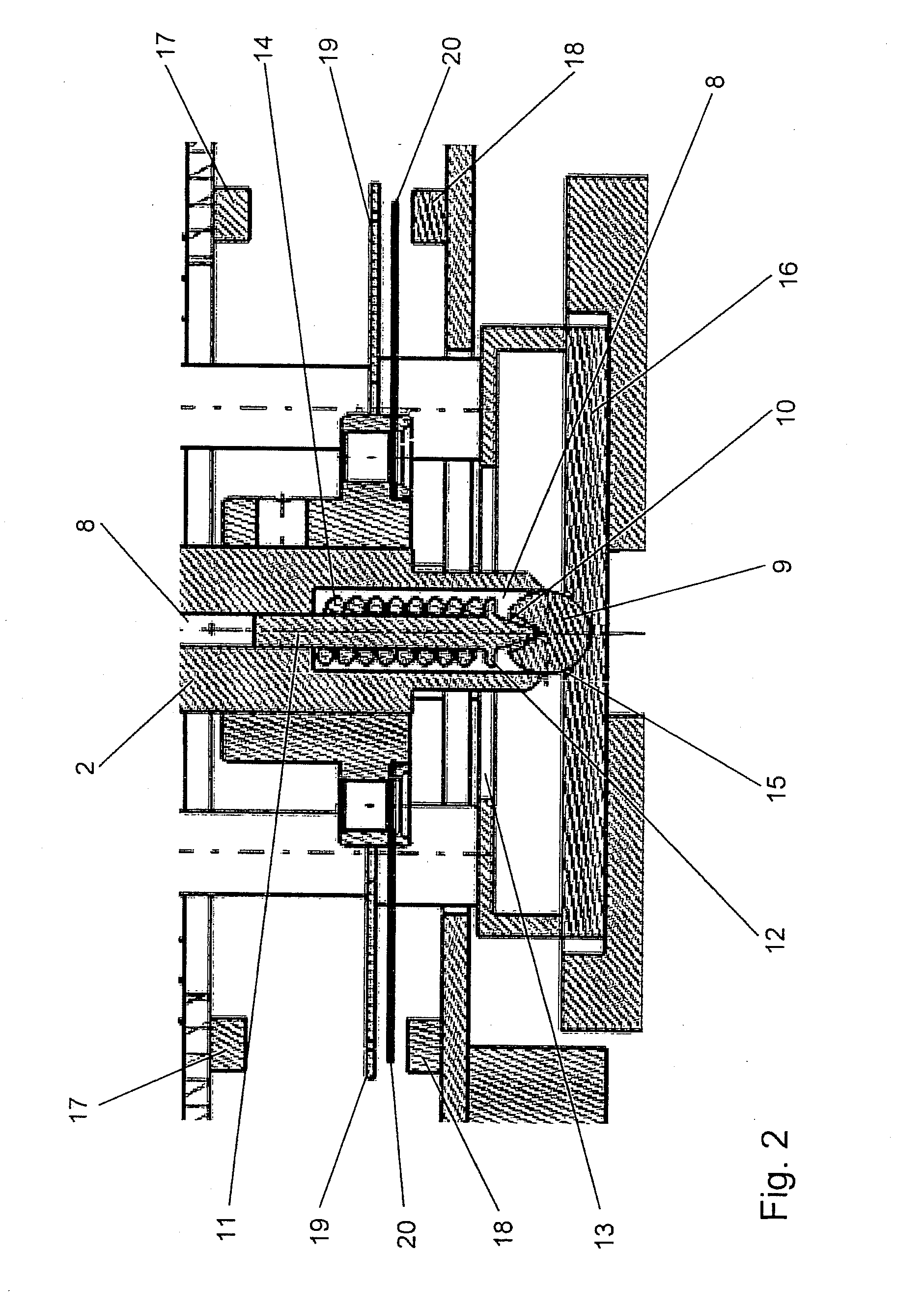
[0024]As is evident from FIG. 1, a lever 2 is supported in articulated fashion in a housing 1. For this purpose, part of the upper half of the lever 2 is enlarged in the shape of a ball, wherein this enlargement 3 is supported in an appropriate bushing 4 with very little play such that the lever 2 can tilt about a center of rotation within the bushing 4. Rotation of the lever 2 about its longitudinal axis is prevented by means of a pin 21 placed axially through the center of rotation of the enlargement. In addition, the lever 2 is guided beneath the enlargement 3 in a cross-shaped switching gate 13, which is attached in the housing 1 and permits four directions of tilt of the lever 2 here, with a right angle being formed between two adjacent direct...
PUM
 Abstract
Description
Claims
Application Information