Housing for an electrically powered device

a technology for electrically powered devices and housing, which is applied in the direction of electrical apparatus casings/cabinets/drawers, coupling device connections, lighting and heating apparatus, etc., can solve the problems of not preventing the electrical connection means from being connected, installation safety issues, and installers not being aware of potential hazards

Active Publication Date: 2013-05-09
KONINKLIJKE PHILIPS ELECTRONICS NV
View PDF11 Cites 6 Cited by
  • Summary
  • Abstract
  • Description
  • Claims
  • Application Information

AI Technical Summary

Benefits of technology

[0006]It is an object of the present invention to provide a housing that fulfils requirements relating to safe handling of the electrically powered device comprised in the housing, and particularly to enable safe installation of the electrically powered device.
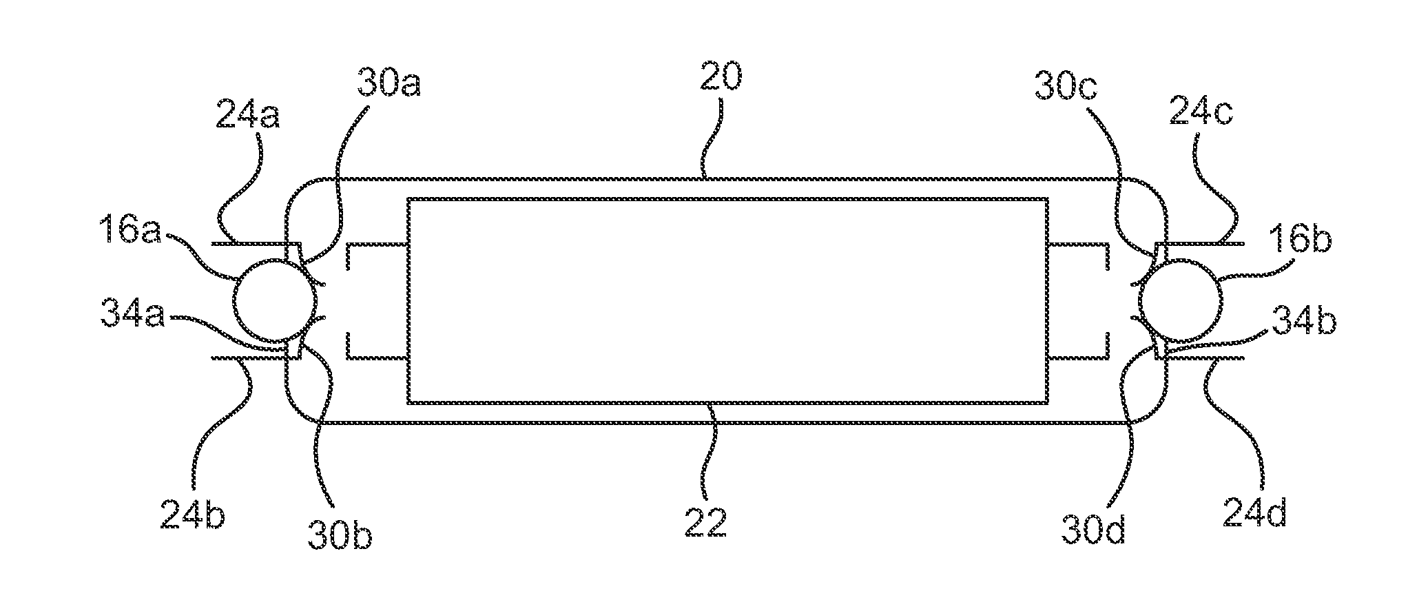
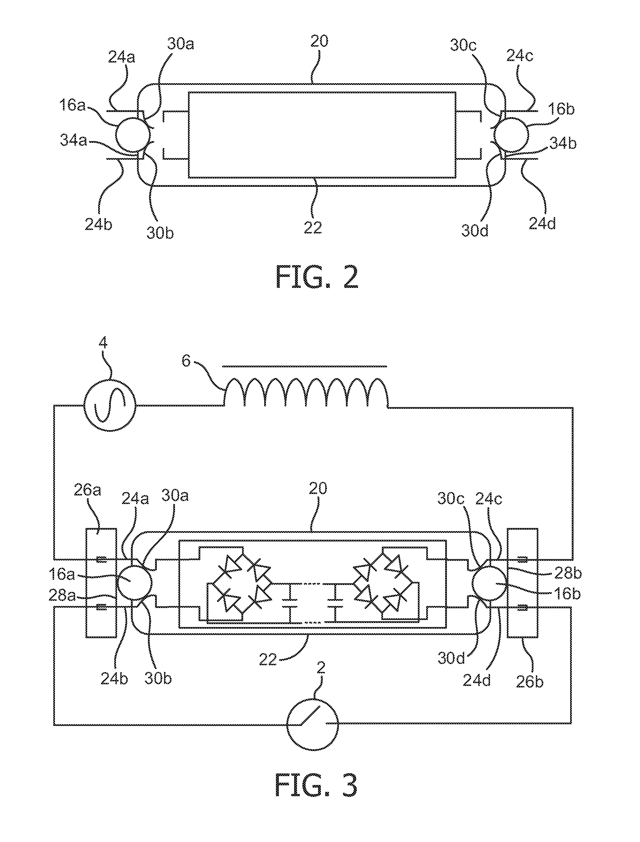
[0008]Advantageously such a housing allows a current to flow between the electrically powered device and the electrical connecting means only when the protruding element is depressed by the front side of the interface means in connecting the housing to the interface means. Thereby there will not be any voltage present at electrical connecting means which are exposed, hence enabling secure installation. Advantageously the disclosed housing thus provides simple mechanical means for enabling secure installation of the electrically powered device.
[0013]Advantageously the electrical connecting means is paired with front sides, thereby enabling even more secure installation. Advantageously, enabling two protruding elements to be pushed by only one front side may allow for a simple and cheap but still effective interface means to be provided. Depending on the number of electrical connections required for the specific application and the geometrical arrangement of the interface, even only one front side may be used as the most simple and cheap but still effective and safe interface means.
[0015]Advantageously the provision of the electrical connecting means at respective ends of the housing may provide for even more secure installation.
[0024]Advantageously the disclosed housing may allow secure installation of a light source.

Problems solved by technology

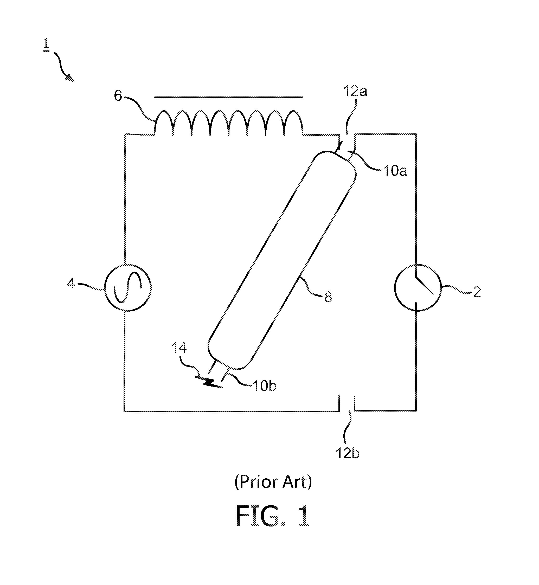
But in other cases this does not prevent the electrical connecting means from being connected to the “wrong” interface means or in a “wrong” way.
Thus, with current solutions, there might be a safety issue during installation.
The potential hazard described above may relate (only) to LED retrofit electrically powered devices, as their internal structure may provide a current path through the electrically powered device.
Hence, due to the nature of the different types of electrically powered devices the installer might not be aware of the potential hazard originating from the uninstalled pins.

Method used


Image

  • Housing for an electrically powered device
  • Housing for an electrically powered device
  • Housing for an electrically powered device

Examples


Embodiment Construction

[0034]The present invention will now be described more fully hereinafter with reference to the accompanying drawings, in which currently preferred embodiments of the invention are shown. This invention may, however, be embodied in many different forms and should not be construed as limited to the embodiments set forth herein; rather, these embodiments are provided for thoroughness and completeness, and fully convey the scope of the invention to the skilled addressee. Like reference characters refer to like elements throughout.

[0035]In order for an electrically powered device to be powered a closed circuit through which electrical current can flow needs to be established. Typical examples of electrically powered devices includes, but are not limited to, light sources, luminaires, LED retrofits of linear TL tubes, and the like. Electrically powered devices are provided with electrical connecting means by which the electrically powered devices can be electrically connected to an interf...


PUM


Abstract

There is provided a housing comprising an electrically powered device and electrical connecting means. The (electrical connecting means of the) housing fits an interface means of an electrical power supply. The housing is provided with one or more protruding elements movable between an idle position and a depressed position. In the idle state the one or more protruding elements prevent an electric current from passing between the electrical connecting means and the electrically powered device. The interface means comprise a front side which interacts with the one or more protruding elements by pushing the one or more protruding elements into the depressed state, thereby enabling an electric current to pass between the electrical connecting means and the electrically powered device exclusively when the housing has been properly installed.

Description

FIELD OF THE INVENTION[0001]The present invention relates in general to a housing for an electrically powered device, and in particular to a housing for an electrically powered device enabling safe installation of the same.BACKGROUND OF THE INVENTION[0002]For a high market penetration of solid state light sources (LED lamps), at the time being, retrofit lamps are considered quite important. This also includes TL tubes. There are some types of housing for such electrically powered devices which have electrical connecting means (for connecting the electrically powered device to the mains power supply) at opposite ends of the housing. Thus during installation one end may still be exposed whilst the other end has been connected to the mains power supply. There are also some types of housing for such electrically powered devices which have all electrical connecting means at one end. In some cases the mechanical design of the housing, may prevent the “right” electrical connecting means fr...

Claims


Application Information

Patent Timeline
Patent Type & Authority Applications(United States)
IPC IPC(8): H05K5/00F21V15/01
CPCH01R33/96F21V15/01F21K9/175F21V25/04F21Y2101/02H05K5/0091F21K9/27F21Y2115/10Y02B20/30H05B45/357H05B47/26
Inventor VAN DER WEL, PIETER
Owner KONINKLIJKE PHILIPS ELECTRONICS NV
Why Eureka
Try Eureka