
Linear solid-state lighting with frequency sensing free of fire and shock hazards

a technology of frequency sensing and solid-state lighting, which is applied in the direction of lighting safety devices, semiconductor devices of light sources, lighting and heating apparatus, etc., can solve the problems of high total cost of ownership, inconvenient maintenance, and inability to identify ballasts and replace incompatible parts

Active Publication Date: 2016-03-01
ALEDDRA INC
View PDF4 Cites 30 Cited by
  • Summary
  • Abstract
  • Description
  • Claims
  • Application Information

AI Technical Summary

Benefits of technology

[0017]A universal linear LED tube (LLT) lamp comprising a housing having two ends, an LED printed circuit board (PCB) with a plurality of LEDs connected as LED arrays, a lens, two bridge rectifiers each having two inputs connecting to two pins of a bi-pin at each end of the lamp, a frequency sensing and control mechanism, an LED driving circuit, and a shock protection mechanism, is used to replace a fluorescent tube in a retrofit or newly-made linear tube lamp fixture that could have an existing electronic ballast or simply an AC mains-ready configuration. When such a universal LLT lamp is installed in the fixture, the frequency sensing and control mechanism can detect input voltage type and make proper and necessary management so that the universal LLT lamp can operate with the existing electronic ballast or simply with the AC mains without operational uncertainty. When such a frequency sensing and control configuration is used with shock protection switches on both ends of the universal LLT lamp, the shock protection switches can effectively block an electric current flowing through the frequency sensing and control mechanism and the LED driving circuit to an exposed bi-pin not yet installed in the fixture sockets, no matter whether the current is from the AC mains or ballast outputs. Therefore, no line voltage or leakage current will possibly appear at the exposed bi-pin during initial installation or re-lamping, thus completely eliminating risks of fire and electric shocks. In an embodiment, the universal lamp can operate not only in a double-ended fixture with an AC voltage from the AC mains or an electronic ballast supplied from the two ends of the lamp but also in a single-ended fixture with an AC voltage from the AC mains supplied from either end of the two ends of the lamp without shock hazards.
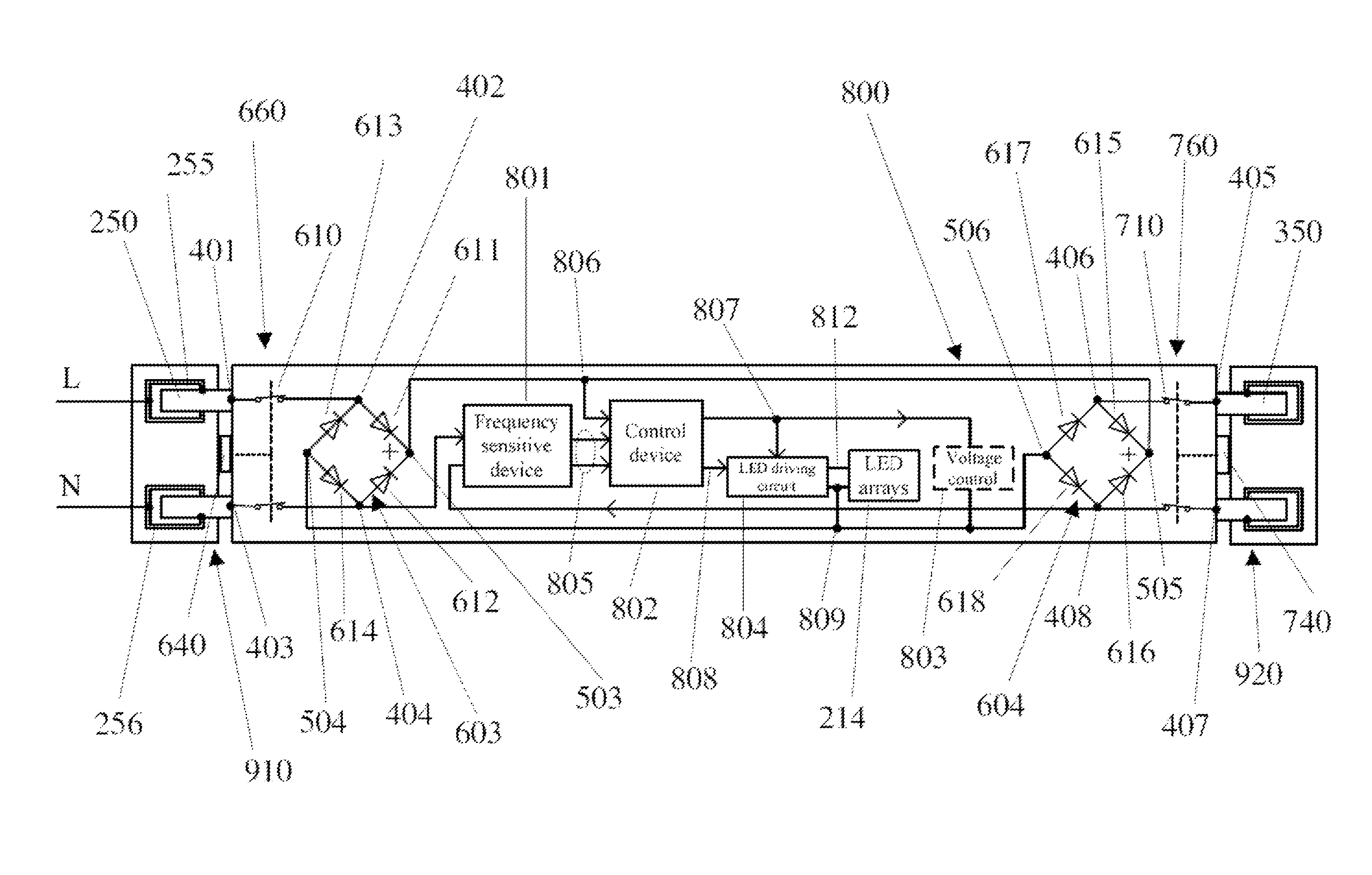
[0018]The frequency sensing and control mechanism comprises a frequency sensitive device and a control device with two inputs each respectively connecting to one of two pins of the bi-pins associated with two ends of the universal LLT lamp. The frequency sensitive device detects frequency of an input voltage and converts it into a signal to send to the control device. The control device receives the signal and controls electric current paths to deliver a power to the LED driving circuit, which then provides an appropriate voltage and current to operate the LED arrays. In this scheme, two outputs with the same polarity of each of the two bridge rectifiers are respectively connected to have a common high electric potential port relative to a common low electric potential port. The electric current paths are reconfigurable according to the frequency detected, either 50˜60 Hz from the AC mains or 40˜50 KHz from an electronic ballast. The LED driving circuit is a modified Buck converter having two high electric potential inputs, comprising an electronic switch, control logics, a current sensing resistor, a capacitor, a diode, and a center-tapped inductor. When the control device determines that input voltage is from the electronic ballast, it makes an electric connection between the common high electric potential port of the bridge rectifiers and the first high electric potential input of the modified Buck converter. When the control device determines that input voltage is from the AC mains, it makes an electric connection between the common high electric potential port of the bridge rectifiers and the second high electric potential input of the modified Buck converter in a way to facilitate the electric current flow into the LED arrays.
[0019]Consumers can safely install such a universal LLT lamp in an existing lamp fixture used to operate a conventional fluorescent tube without operational uncertainty and electric shock or fire hazards, no matter how the fixture is wired, single-ended AC mains, double-ended AC mains, or electronic ballast. The universal LLT lamp can immediately be used with an existing electronic ballast in a fixture without rewiring. When the ballast dies, consumers may choose to replace it with a new one at cost or just to bypass it and to electrically connect the fixture as an AC mains-operable one. In the latter case, the consumers can just install the universal LLT lamp back into the fixture without worrying about possible electric shock hazard that may occur when they accidentally touch an exposed bi-pin on the other end of the lamp, or possible fire hazard due to misapplications of a power supplied to the lamp.

Problems solved by technology

But the fact is that total cost of ownership for this approach is high regardless of very low initial cost.
If the existing ballast is not compatible with the ballast-compatible LLT lamp, the consumer will have to replace the ballast.
Some facilities built long time ago incorporate different types of fixtures, which requires extensive labor for both identifying ballasts and replacing incompatible ones.
Maintenance will be complicated, sometimes for lamps and sometimes for ballasts.
The labor costs and long-term maintenance costs will be unacceptable to end users.
In the long run, ballast-compatible LLT lamps are more expensive and less efficient than self-sustaining AC mains-operable LLT lamps.
However, such LLT lamps operating at the AC mains, 110, 220, or 277 VAC, have one construction issue related to product safety and needed to be resolved prior to wide field deployment.
This kind of LLT lamps always fails a safety test, which measures through lamp leakage current.
Because the line and the neutral of the AC mains apply to both opposite ends of the tube when connected, the measurement of current leakage from one end to the other consistently results in a substantial current flow, which may present a risk of shock during re-lamping.
However, such an LLT lamp can only operate with the AC mains and is not compatible with an electronic ballast.
Misapplications of power supply connections for conventional LLT lamps that substitute for linear fluorescent lamps are main causes of fire and electric shock hazards today, where the conventional LLT lamps are incorrectly connected to a supply source, the lamp base is either inserted incorrectly into a lamp holder or inserted into a lamp holder not intended for the conventional LLT lamp, or a conventional LLT lamp is connected to lamp holders with supply connections that do not match the lamp configuration.
All of these misapplications may result in fire and shock hazards.
However, any incompatible combinations of the conventional LLT lamps and the fixtures lead to failure of operation.
These kinds of operational uncertainty, inconvenience, and possible hazards may severely affect the willingness of the consumers to adopt conventional LLT lamps.

Method used


Image

  • Linear solid-state lighting with frequency sensing free of fire and shock hazards
  • Linear solid-state lighting with frequency sensing free of fire and shock hazards
  • Linear solid-state lighting with frequency sensing free of fire and shock hazards

Examples


Embodiment Construction

[0027]FIGS. 3-4 are block diagrams of a universal LLT lamp configured in a double-ended and a single-ended fixture according to the present disclosure. The universal LLT lamp 800 comprises a housing having two ends; two lamp bases 660 and 760 having respective bi-pins 250 and 350 at each end of the housing; two actuation mechanisms 640 and 740 of shock protection switches 610 and 710 respectively in the two lamp bases 660 and 760; two bridge rectifiers 603 and 604; a frequency sensing and control mechanism comprising a frequency sensitive device 801 and a control device 802; a voltage control device 803; an LED driving circuit 804 having two inputs 807 and 808 and a current return port 809; and LED arrays 214 on an LED PCB.

[0028]Each bridge rectifier comprises four diodes, 611, 612, 613, and 614 for the first bridge rectifier 603 and 615, 616, 617, and 618 for the second bridge rectifier 604. In the first bridge rectifier 603, the four diodes are interconnected with four input / outpu...


PUM


Abstract

A linear light-emitting diode (LED)-based solid-state universal lamp using a frequency sensing and control mechanism operates normally with both an electronic ballast and the AC mains. The frequency sensing and control mechanism automatically detects voltage types associated with output voltages from the ballast and the AC mains in a single-ended or a double-ended lamp fixture and makes proper management so that the universal lamp works for either case and in either fixture without operational uncertainty. When two shock protection switches are used in two lamp bases, the universal lamp fully protects a person from possible electric shock during initial installation and re-lamping.

Description

CROSS-REFERENCE TO RELATED APPLICATIONS[0001]This application is a continuation-in-part (CIP) of U.S. patent application Ser. No. 14 / 135,116, filed Dec. 19, 2013 and currently pending, which is incorporated herein by reference in its entirety.BACKGROUND[0002]1. Technical Field[0003]The present disclosure relates to linear light-emitting diode (LED) lamps that work with linear tube lamp fixtures configured to electrically connect either instant-start electronic ballast or the AC mains, and more particularly to a universal, shock and fire hazard-free linear LED tube lamp with a shock-protection mechanism.[0004]2. Description of the Related Art[0005]Solid-state lighting from semiconductor light-emitting diodes (LEDs) has received much attention in general lighting applications today. Because of its potential for more energy savings, better environmental protection (with no hazardous materials used), higher efficiency, smaller size, and longer lifetime than conventional incandescent bul...

Claims


Application Information

Patent Timeline
Patent Type & Authority Patents(United States)
IPC IPC(8): H05B37/02H05B33/08F21V25/04F21K99/00F21Y101/02H05B44/00
CPCH05B33/0803F21K9/175F21V25/04H05B33/0806F21Y2101/02Y02B20/341F21Y2115/10F21K9/278Y02B20/30H05B45/305H05B45/3578H05B45/50H05B47/26
Inventor HSIA, CHUNGHOSHEN, PAI-SHENG
Owner ALEDDRA INC
Learn More