
Installation tool for irrigation emitter barbs with cutter

a technology of emitter barbs and installation tools, which is applied in the field of tools for installing irrigation emitter barbs, can solve the problems of not working with standard irrigation emitter barbs, still requires the handling of sharp piercing points, and injuring workers, and achieves the effect of safe installation of irrigation emitter barbs

Inactive Publication Date: 2007-03-06
MYERS MICHAEL
View PDF15 Cites 35 Cited by
  • Summary
  • Abstract
  • Description
  • Claims
  • Application Information

AI Technical Summary

Benefits of technology

"The invention is a tool that can be used to install irrigation emitter barbs in irrigation tubing. It can also be used to trim the tubing as needed. The tool is designed to safely install the emitter barbs. The technical effects of this invention are improved efficiency and accuracy in the installation of irrigation emitter barbs, as well as improved safety during the installation process."

Problems solved by technology

While irrigation emitter barbs can be installed by hand, the sharp piercing points can cause injury to workers.
However, installation still requires handling of the sharp piercing points by the installer.
However, the Costa tool requires use of the specific Costa fitting to properly function and thus does not function with standard irrigation emitter barbs.
It does not provide a mechanism for inserting irrigation barbs into said tubing.
None of the known prior art disclose the combination set forth herein.

Method used


Image

  • Installation tool for irrigation emitter barbs with cutter
  • Installation tool for irrigation emitter barbs with cutter
  • Installation tool for irrigation emitter barbs with cutter

Examples


Embodiment Construction

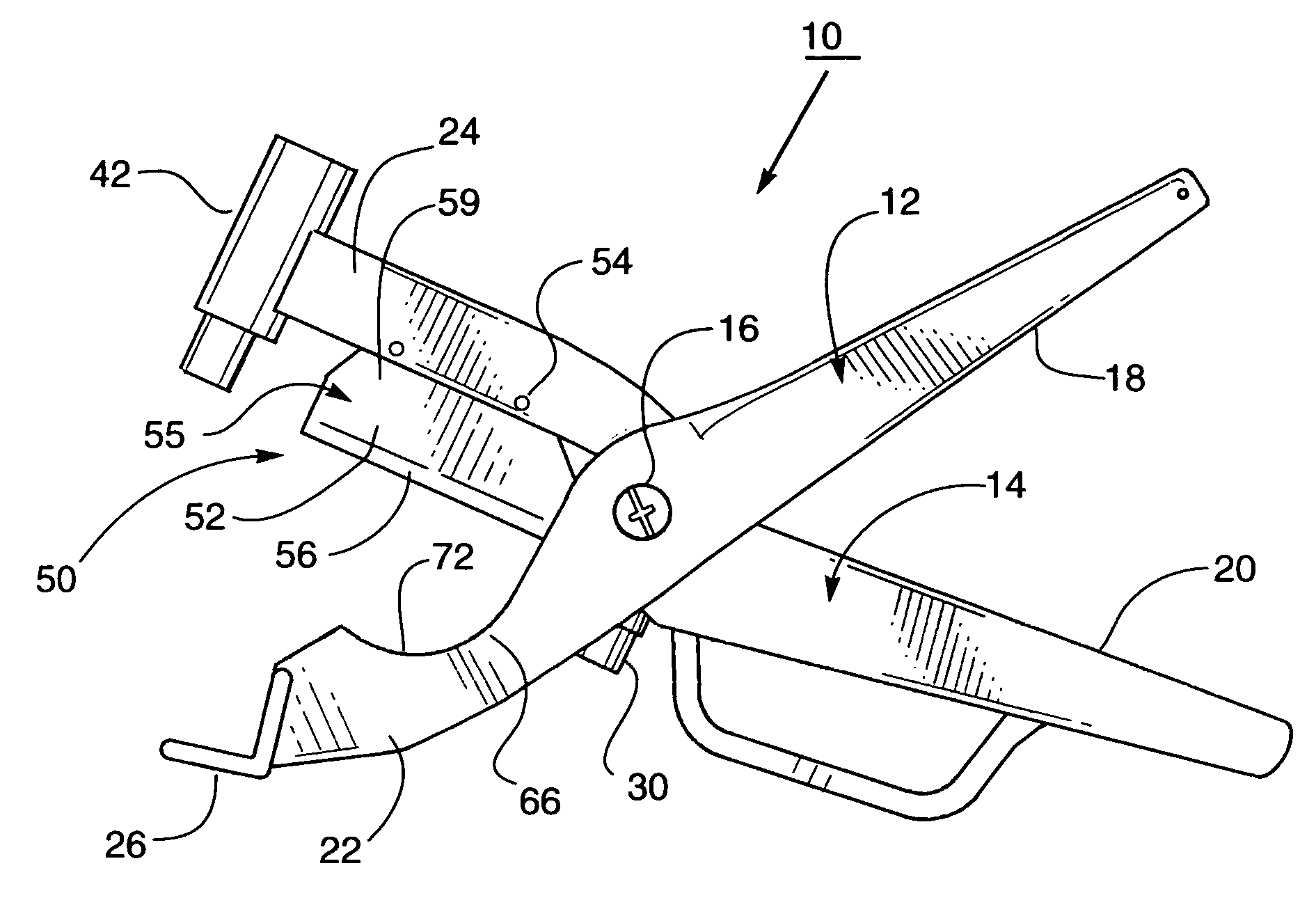
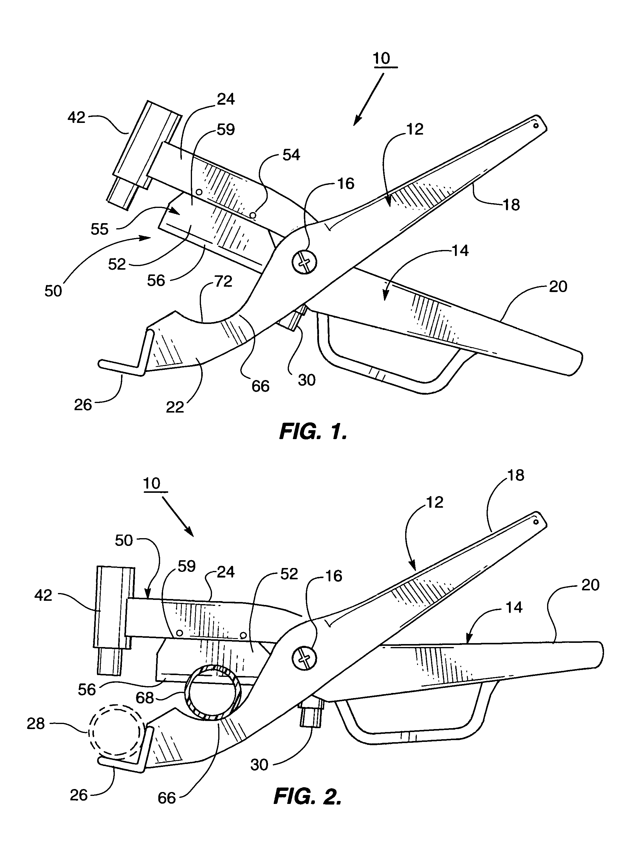
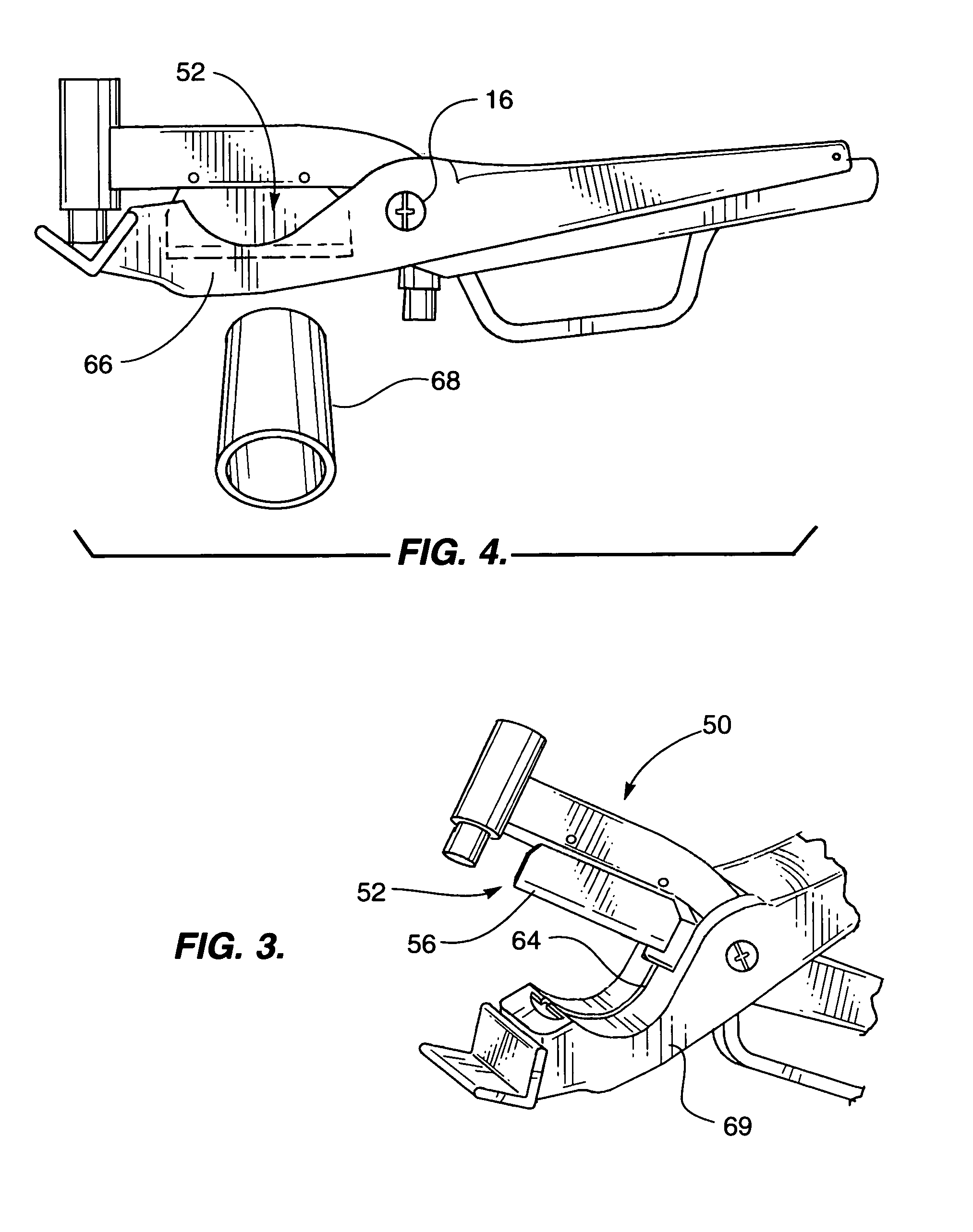
[0026]Referring more particularly to the drawings by characters of reference, FIGS. 1–3 disclose one embodiment of an irrigation tool 10. Irrigation tool 10 comprises a cradle member 12 and a punch member 14. Cradle member 12 and punch member 14 are arranged in crossed relation and pivotally connected intermediate their ends at pivot 16. The portions of cradle member 12 and barb holder member 14 extending rearwardly from pivot 16 constitute cradle handle 18 and punch handle 20, respectively. The portions of cradle member 12 and punch member 14 extending forwardly from pivot 16 constitute cradle jaw 22 and punch jaw 24, respectively.

[0027]It will be understood by those skilled in the art that other plier type arrangements would be applicable to the present invention. For example, a double pivot vice grip plier arrangement would also be suitable for use in the present invention.

[0028]Mounted at end of cradle jaw 22 is a cradle 26 which is an upwardly opening V-shape and elongated widt...


PUM

PropertyMeasurementUnit
diameteraaaaaaaaaa
FLEXIBLEaaaaaaaaaa
flexibleaaaaaaaaaa

Abstract

A tool installs barb emitters in irrigation tubing. The tool has a cradle which receives irrigation tubing and a punch mounted opposite the cradle. The punch has a first cylinder and a second cylinder telescopically received within the first cylinder. The first cylinder has a cap at the upper end and an annular ring extending inwardly from to partially occlude the lower end. The second cylinder includes a second cap at the upper end which slidably engages the first cylinder and is resiliently urged by a spring against the annular ring. The cap has a punch holder extending downwardly therefrom. A needle has a sharp tip extending downwardly from the punch holder through the second cap to a point within the second cylinder when the spring is fully extended and beyond the second cylinder when the spring is fully compressed. One of the jaws has a knife blade extending from the other end thereof opposite. The of the jaws defines a semi-circular concave anvil at the other end. The anvil has an axially extending slot therein which receives the cutting edge of said knife blade when the handles are closed together.

Description

TECHNICAL FIELD[0001]This invention relates to the field of irrigation tools, and, more particularly, to a tool for installing irrigation emitter barbs in irrigation tubing in combination with a cutter.BACKGROUND OF THE INVENTION[0002]It is common to use plastic tubing to distribute water to various locations for irrigation purposes. In such use, hollow irrigation emitter barbs are mounted as desired on the plastic tubing. Such barbs are hollow allowing the water contained within the tubing to be distributed, or emitted, as desired. Small diameter flexible tubing can be mounted on the barbs to place the water where desired.[0003]Irrigation emitter barbs are generally symmetrical and are provided with sharp piercing points at both ends to penetrate the wall of the tubing. Further, enlarged heads are provided to impede the withdrawal of the barb from the tubing. While irrigation emitter barbs can be installed by hand, the sharp piercing points can cause injury to workers. In fact, the...

Claims


Application Information

Patent Timeline
Patent Type & Authority Patents(United States)
IPC IPC(8): B23P19/02
CPCA01G25/023B25B7/02Y10T29/539Y10T29/53909Y10T29/53896
Inventor MYERS, MICHAEL
Owner MYERS MICHAEL
Learn More