Plug-in module for plugging in and/or pulling out of a module rack

a plug-in module and rack technology, which is applied in the direction of electrical apparatus, coupling parts engagement/disengagement, cabinet/drawer, etc., can solve the problems of not being able to secure the module in the completely pivoted-out end position, allowing the lever to pivot downward unintentionally, and not being able to fully plug the module into the rack. , to achieve the effect of preventing wear, facilitating production, and improving the operating comfort of the lever

Inactive Publication Date: 2005-01-20
SCHROFF GMBH
View PDF9 Cites 28 Cited by
  • Summary
  • Abstract
  • Description
  • Claims
  • Application Information

AI Technical Summary

Benefits of technology

[0008] Thus, it is the object of the present invention to create a plug-in module for which the lever pull in the completely pivoted-out position can be locked in place reliably with simple mechanical means, wherein it should be possible to release the locking easily and without problems during the insertion of the plug-in module into the rack.

Problems solved by technology

The problem with the upper lever pull is that the long lever arm, designed as handle arm, drops down as a result of gravity, thus allowing the lever pull to pivot downward unintentionally.
As a result, the lever pull obstructs the insertion of the plug-in module and the module cannot be plugged completely into the rack while the lever is in this position.
However, a securing of the lever in the completely pivoted-out end position is not planned and is also not possible with the proposed latching means.
In practical operations, however, springs of this type have proven unsuitable since they will become overextended and soft over time, thus no longer ensuring a reliable holding of the lever pull.
However, the operator frequently uses uncontrolled force to overcome the spring force and the lever pull is pivoted-in too early.

Method used


Image

  • Plug-in module for plugging in and/or pulling out of a module rack
  • Plug-in module for plugging in and/or pulling out of a module rack
  • Plug-in module for plugging in and/or pulling out of a module rack

Examples


Embodiment Construction

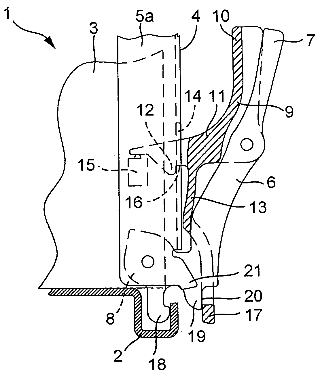
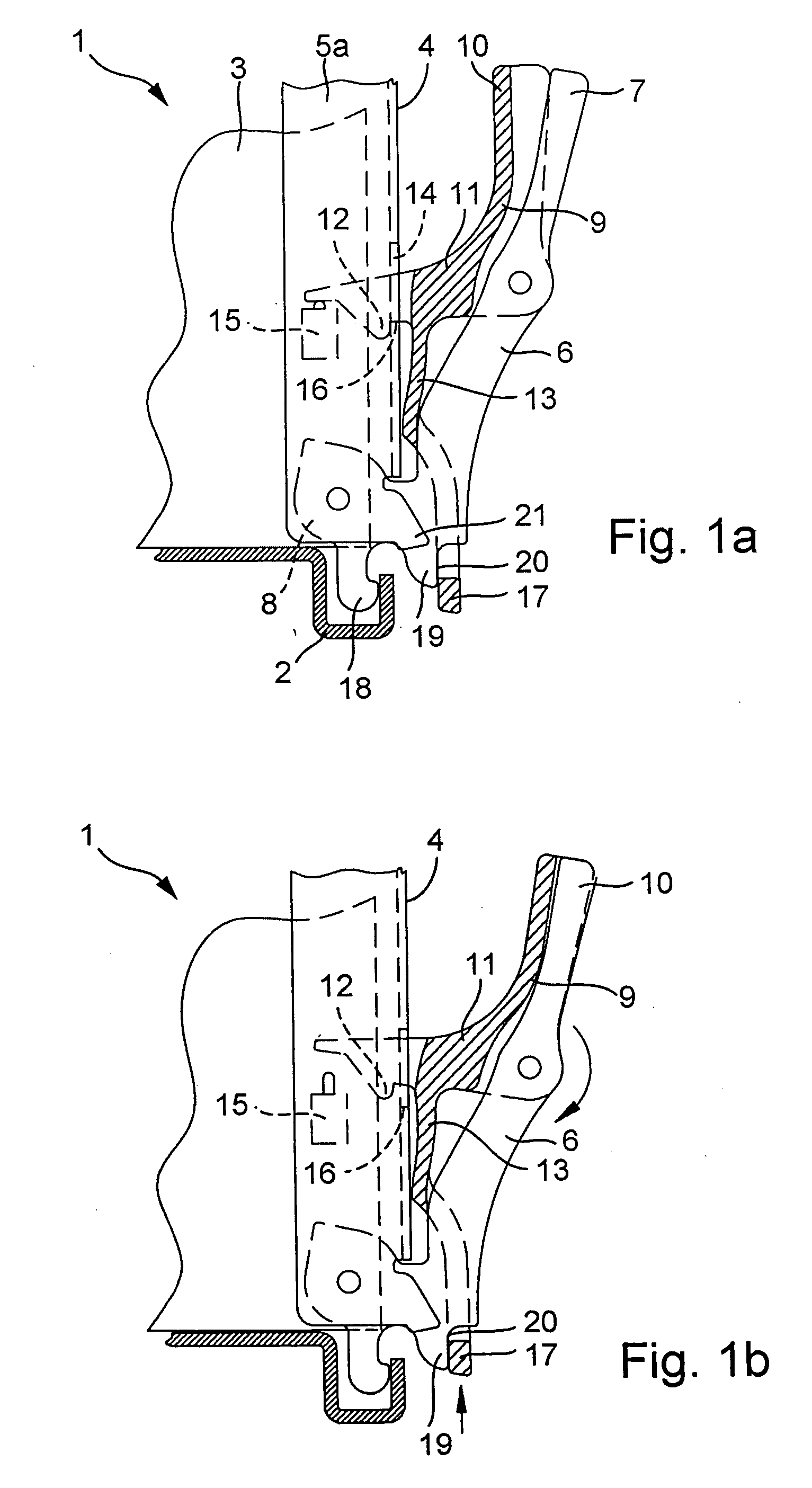
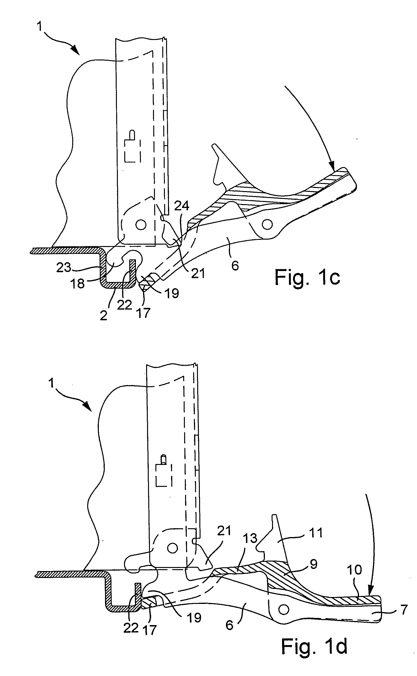
[0035]FIGS. 1a to 1d clearly illustrate the operation of pulling a plug-in module 1 out of a module rack, wherein only the lower front stop edge 2 of the rack can be seen, which may take the form of a module rail and / or module bar.

[0036]FIG. 1a shows the plug-in module 1 in the position where it is completely inserted into the rack. The plug-in module 1 comprises a circuit board 3, a front panel 4 with angled side part 5a and a lever pull 6, arranged such that it can turn in the frontal region of the plug-in module 1. The lever pull 6 has a long, upward-extended handle arm 7 and a shorter lever arm 8.

[0037] A locking lever 9 is arranged such that it can turn on the handle arm 7. The locking lever 9 comprises an activation arm 10 and a detent 11, which is arranged approximately at a 90 degree angle to the activation arm 10. A detent nose 12 is formed onto the detent 11, wherein the detent 11 is also provided with a locking tab 13 that extends downward, approximately parallel to the...


PUM


Abstract

A plug-in module to be plugged in and / or pulled out of a module rack provided with at least one front stop edge, comprising a lever pull with handle arm and lever arm which is positioned pivoting in the frontal region of the plug-in module. A locking lever is attached articulated and such that it can rotate to the handle arm of lever pull. The locking lever turns an elastic locking tab. A corresponding locking profile is arranged in the frontal region of the plug-in module, wherein the locking tab engages behind the locking profile if the lever pull is pivoted out completely and thus prevents the lever pull from pivoting.

Description

CROSS-REFERENCE TO RELATED APPLICATION [0001] This application claims the priority of European Patent Application No. 03 016 291.1, filed on Jul. 18, 2003, the subject matter of which is incorporated herein by reference. BACKGROUND OF THE INVENTION [0002] The invention relates to a plug-in module for plugging in and / or pulling out of a rack having at least one front stop edge. The plug-in module comprises a lever pull that is positioned pivoting in the front region of the plug-in module and is provided with a handle arm and a lever arm. [0003] At the back end, plug-in modules are provided with a multi-pole connector which is plugged into a corresponding connector strip on the backplane of the module rack. Enormous forces are required for the connecting and disconnecting of the plug-in connection. For this, the plug-in modules are generally provided in the frontal region with a lower and an upper lever pull, designed for inserting the plug-in modules into and / or removing them from th...

Claims


Application Information

Patent Timeline
Patent Type & Authority Applications(United States)
IPC IPC(8): H05K7/14
CPCH05K7/1414H05K7/1409
Inventor JOIST, MICHAEL
Owner SCHROFF GMBH
Why Eureka
Try Eureka