Indexable cutting insert with positive axial rake angle and multiple cutting edges

a technology of axial rake angle and indexable cutting insert, which is applied in the direction of cutting inserts, shaping cutters, manufacturing tools, etc., can solve the problem that cutting inserts cannot take full advantage of the greater cutting for

Inactive Publication Date: 2008-09-18
KENNAMETAL INC
View PDF17 Cites 68 Cited by
  • Summary
  • Abstract
  • Description
  • Claims
  • Application Information

AI Technical Summary

Problems solved by technology

By mounting the cutting inserts with a negative axial rake angle, the cutting inserts cannot take complete advantage of the greater cutting

Method used


Image

  • Indexable cutting insert with positive axial rake angle and multiple cutting edges
  • Indexable cutting insert with positive axial rake angle and multiple cutting edges
  • Indexable cutting insert with positive axial rake angle and multiple cutting edges

Examples


Embodiment Construction

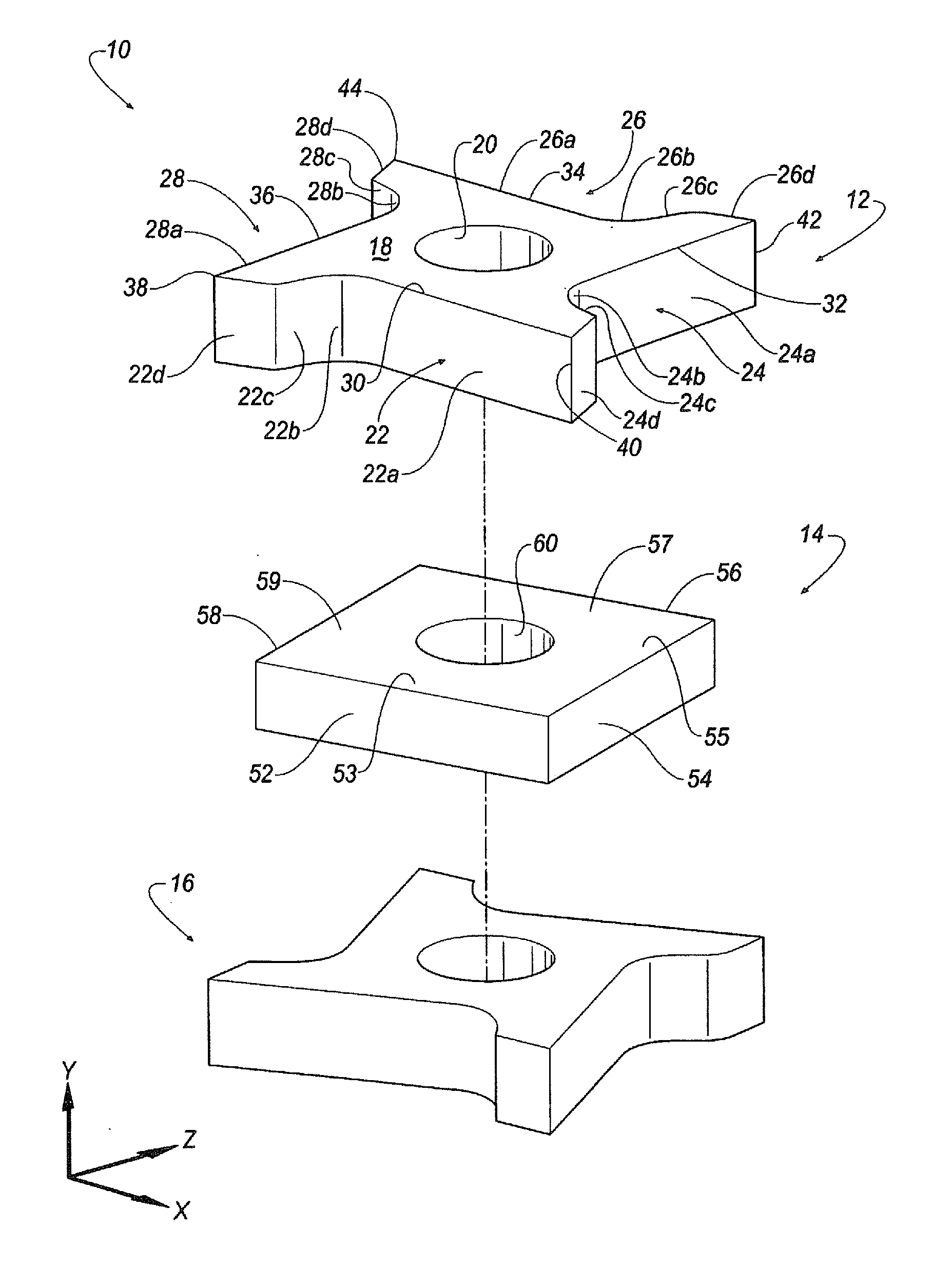
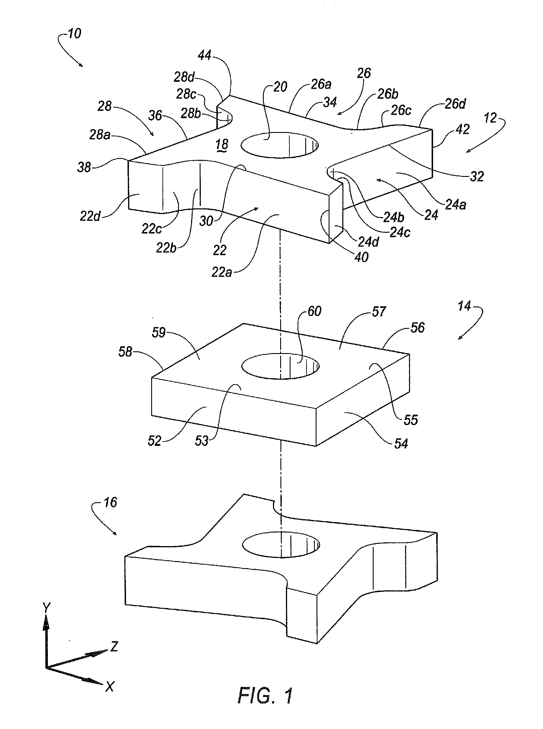
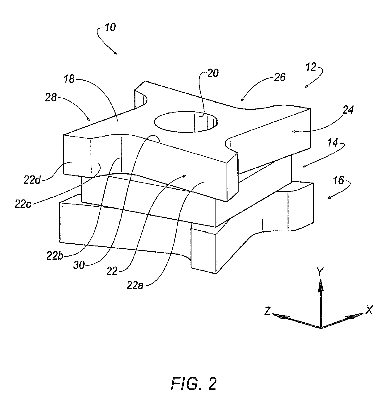
[0026]Referring to the drawings, wherein like reference characters represent like elements, FIGS. 1-4 show a general design concept for creating an indexable cutting insert with positive axial rake and multiple cutting edges, shown generally at 10, according to the invention. In general, the design concept for creating the cutting insert 10 includes three building blocks or components: a first component, shown generally at 12, a center or second component, shown generally at 14, disposed between the first component 12 and a third component shown generally at 16. The third component 16 is substantially identical to the first component 12, with the third component 16 being mirror symmetric to the first component 12 when rotated one hundred eighty (180) degrees about the vertical or y-axis. For brevity, only the first component 12 will be discussed in detail below.

[0027]The first component 12 is generally polygonal in shape. In the illustrated embodiment, the first component 12 include...


PUM

PropertyMeasurementUnit
Angleaaaaaaaaaa
Angleaaaaaaaaaa
Angleaaaaaaaaaa

Abstract

An indexable cutting insert includes a first component with an outer or top surface and side surfaces. A third component is mirror symmetric with respect to the first component about a vertical or y-axis of the cutting insert. A second component is disposed between the first and third components. Multiple cutting edges are defined at an intersection between the side surfaces and the top surface, wherein the cutting edges define a positive axial rake angle. In one embodiment, the first and third components are in the shape of a polygonal with a star appearance, and the second component is in the shape of a square. The first and third components are offset from one another by a first offset angle, while the second component is offset from the first and third components by a second offset angle to allow the cutting insert to be indexable.

Description

CROSS REFERENCE TO RELATED APPLICATIONS[0001]This application is a continuation-in-part of U.S. application Ser. No. 11 / 471,046 filed Jun. 20, 2006, which will issue as U.S. Pat. No. 7,357,604 on Apr. 15, 2008.BACKGROUND OF THE INVENTION[0002]Tangential cutting inserts, also known as on-edge, or lay down, cutting inserts, are oriented in an insert holder in such a manner that during a cutting operation on a workpiece the cutting forces are directed along a major (thicker) dimension of the cutting insert. An advantage of such an arrangement being that the cutting insert can withstand greater cutting forces than when oriented in such a manner that the cutting forces are directed along a minor (thinner) dimension of the cutting insert.[0003]Currently, double-side indexable cutting inserts with multiple cutting edges are relegated to having negative axial rake angles for cutting clearance. By mounting the cutting inserts with a negative axial rake angle, the cutting inserts cannot take ...

Claims


Application Information

Patent Timeline
IPC IPC(8): B23B27/16B23C5/20
CPCB23B2200/3681B23C5/207B23C2200/125B23C2200/208Y10T407/23B23C2200/367B23C2210/163B23C2270/14B23C2200/286B23C5/202
Inventor CRAIG, KAREN ANNE
Owner KENNAMETAL INC
Why Eureka
Try Eureka