Punch/binding machine and binding module thereof

Inactive Publication Date: 2008-09-18
ZIPSHADE INDAL I CORP
View PDF0 Cites 4 Cited by
  • Summary
  • Abstract
  • Description
  • Claims
  • Application Information

AI Technical Summary

Benefits of technology

[0017]The present invention has the following advantages. The binding module is formed by stacking three plates, i.e., the upper board, the moving seat, and the lower board, thus having a small number of components and being easily assembled. In addition, the moving seat only moves back and fo

Problems solved by technology

In addition, the moving seat only moves back and forth, thu

Method used


Image

  • Punch/binding machine and binding module thereof
  • Punch/binding machine and binding module thereof
  • Punch/binding machine and binding module thereof

Examples


Example

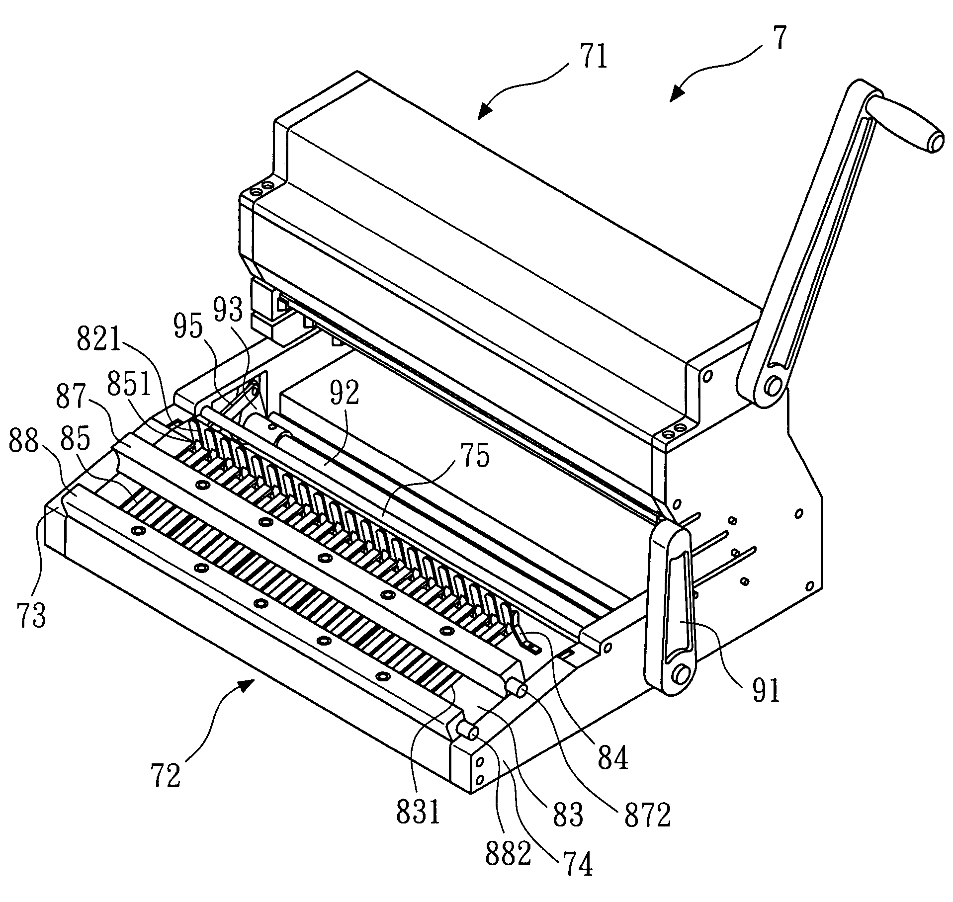
[0032]FIG. 8 shows a perspective view of a punch / binding machine according to the present invention. The punch / binding machine 7 of the present invention includes a punching mechanism 71 and a binding mechanism 72. FIG. 9 shows an exploded perspective view of a binding mechanism of the punch / binding machine according to the present invention. The binding mechanism 72 of the punch / binding machine 7 includes a body (including a left-side body 73 and a right-side body 74), a binding module 8, and a transmission device 9.

[0033]The left-side body 73 and the right-side body 74 are the housing of the binding mechanism 72, in which a plurality of positioning rods 75 is used to position and form an accommodation space to accommodate or support the binding module 8 and the transmission device 9.

[0034]The binding module 8 includes a fixing rod 81, a fixed comb plate 82, an upper board 83, a guide element 84, a moving seat 85, and a lower board 86. Two ends of the fixing rod 81 are respectively...


PUM


Abstract

The present invention relates to a punch/binding machine and a binding module thereof. The punch/binding machine includes a transmission device, a body, and a binding module. The transmission device receives an external force. The body is used to support the transmission device. The binding module includes a fixing rod, a fixed comb plate, an upper board, a guide element, a moving seat, and a lower board. Two ends of the fixing rod are fixed on the body. The fixed comb plate has a plurality of fixing combs, and each of the fixing combs has a flute. The upper board has a plurality of slot apertures for the fixing combs to pass through. The guide element is located on one side of the upper board in order to push a plastic comb into the flutes of the fixing combs. The moving seat has a plurality of shifting rods for pulling the plastic comb. At least one end of the moving seat is connected to the transmission device, so as to be driven by the transmission device. The lower board is located below the moving seat for providing the moving seat to slide on the surface thereof. Thereby, the binding module is formed by stacking three plates, which has a small number of components and is easily assembled.

Description

BACKGROUND OF THE INVENTION[0001]1. Field of the Invention[0002]The present invention relates to a punch / binding machine, and more particularly to a punch / binding machine for loose-leaf papers and a binding module thereof.[0003]2. Description of the Related Art[0004]FIGS. 1 and 2 show a schematic assembly view and a schematic exploded view of a first-type binding mechanism of a conventional punch / binding machine for loose-leaf papers disclosed in U.S. Pat. No. 5,211,522. The conventional first-type binding mechanism 1 is used to pull a plastic comb 2 (FIG. 3). The conventional first-type binding mechanism 1 includes a binding module 10 and a transmission device 18. The binding module 10 includes a pushing board 11, a lower board 12, a moving seat 13, and an upper board 14. The transmission device 18 includes a handle 15, a link 16, and two eccentric cams 17.[0005]The pushing board 11 has two guide shafts 111, a plurality of lower blocks 112, and a plurality of upper blocks 113. The ...

Claims


Application Information

Patent Timeline
IPC IPC(8): B42B9/00
CPCB42B5/103
Inventor CHENG, LI-MINGTSAI, KUE-LINLIAW, SHI-MO
Owner ZIPSHADE INDAL I CORP
Why Eureka
Try Eureka