Machine having camera and mounting strategy therefor

Active Publication Date: 2008-09-25
CATERPILLAR INC
View PDF21 Cites 20 Cited by
  • Summary
  • Abstract
  • Description
  • Claims
  • Application Information

AI Technical Summary

Problems solved by technology

Operators may thus now be required to have a relatively greater field of view than in the past, while changes in machine design have made this all the more challenging to accomplish.
In such a position the camera risks damage from debris, or may be harmed by rain or dust.
In addition, the camera itself becomes another impediment to the operator's view towards the rear of t

Method used


Image

  • Machine having camera and mounting strategy therefor
  • Machine having camera and mounting strategy therefor
  • Machine having camera and mounting strategy therefor

Examples


Embodiment Construction

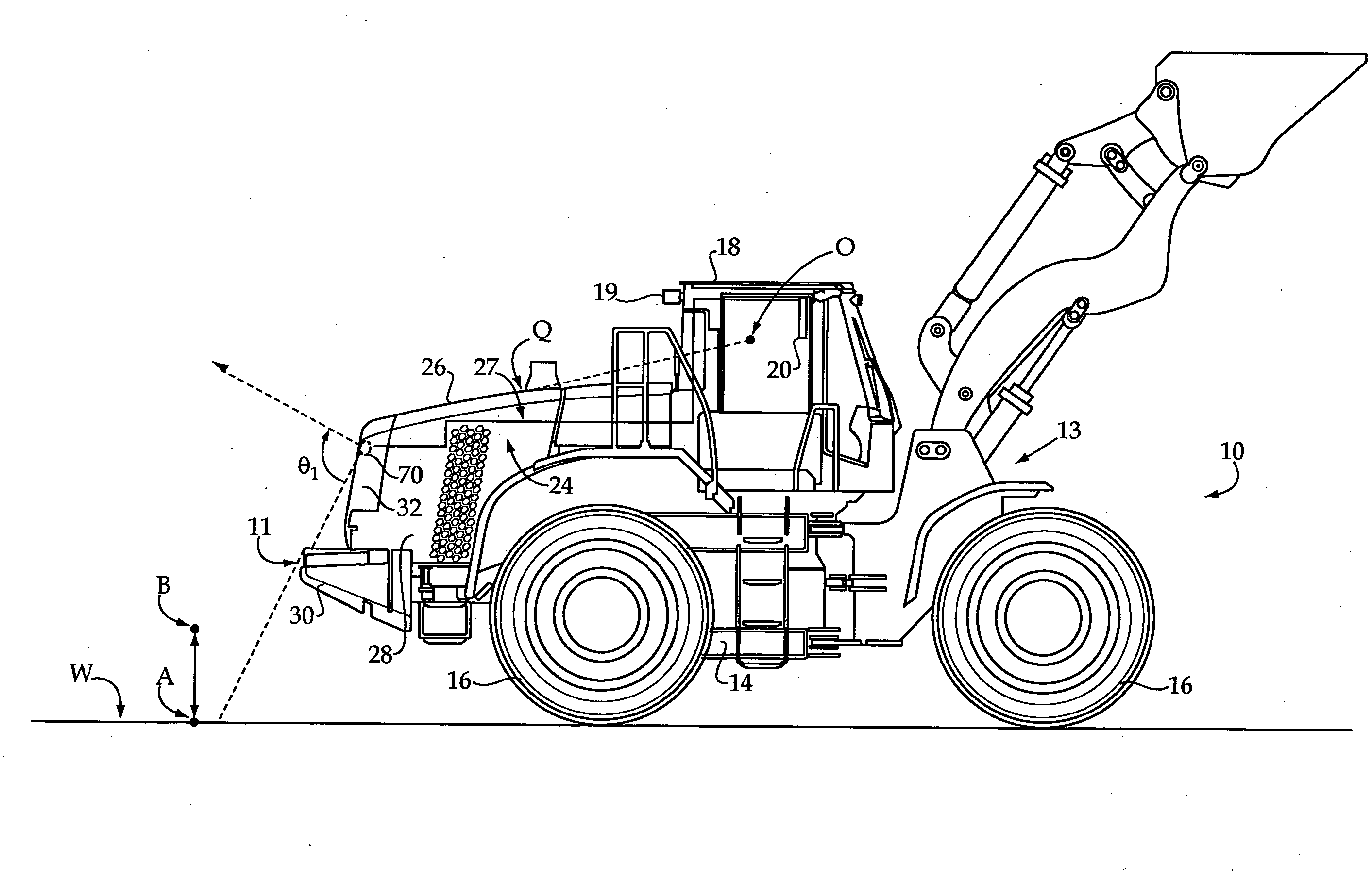
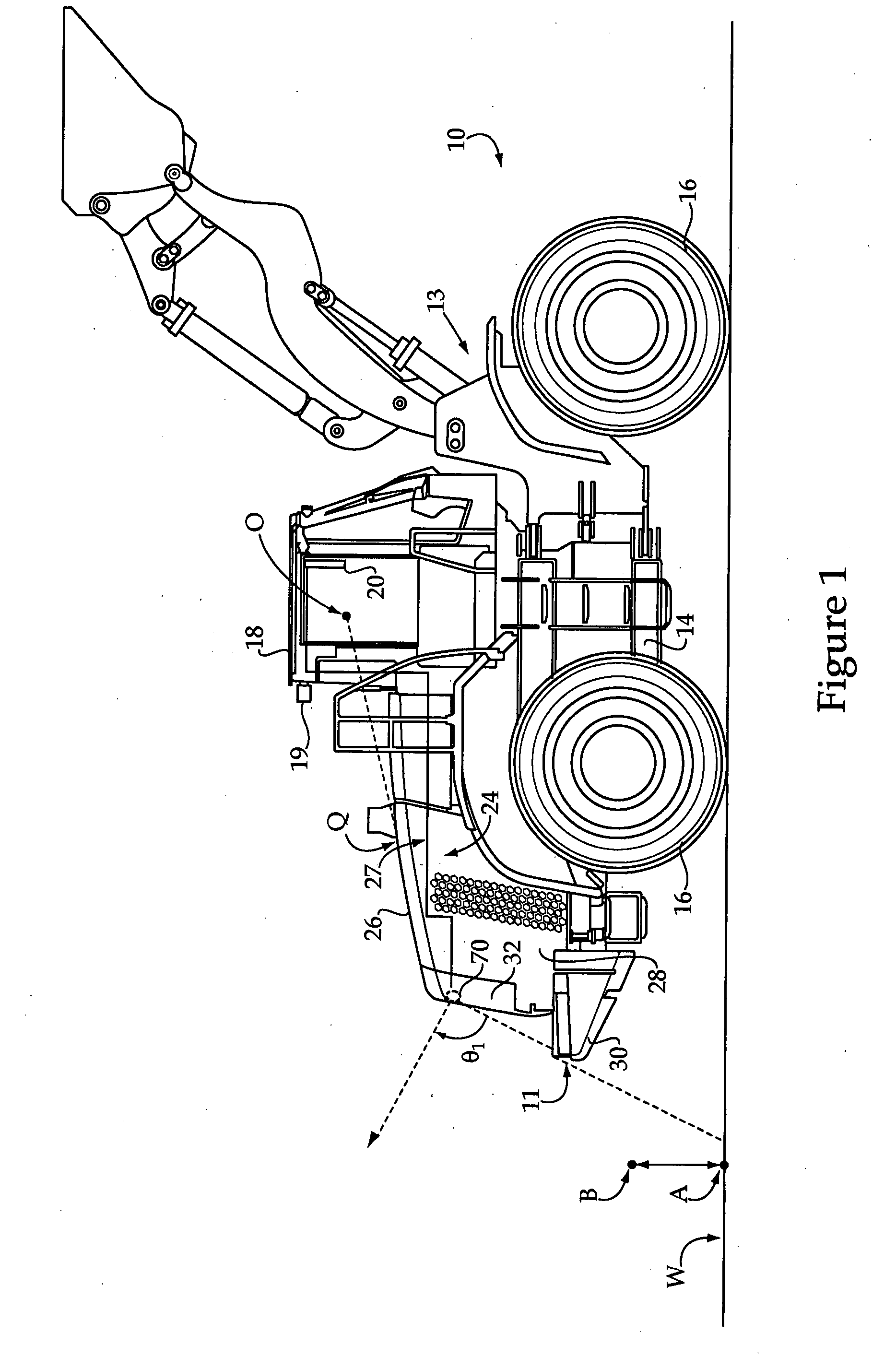
[0020]Referring to FIG. 1, there is shown a side view of a machine 10 according to the present disclosure. Machine 10 is depicted as a wheel loader, having front and back sets of ground engaging elements such as wheels 16. The present disclosure shall be explained by making exemplary reference to its application on a wheel loader. However, the application of the present disclosure is not limited to wheel loaders. Those of ordinary skill in this art will be able to apply the present disclosure to other machines such as track-type machines, trucks, motor graders and many others. Machine 10 may include a camera 70, for example a rearview camera, configured for viewing areas behind machine 10. In other embodiments, or with other machine types, camera 70 might be configured for viewing to the front, or some other direction from machine 10. Camera 70 will typically be coupled with an electrical system 24 of machine 10 and configured to transmit data to a display screen 20 mounted in an op...


PUM


Abstract

A machine includes a frame having ground engaging elements for propelling a machine, and a body mounted to the frame. The body includes a plurality of body components, one of which is contoured for mounting a camera that includes a continuous face and a pocket each formed in an outer surface thereof. The method of assembling a machine includes molding a unitary body component for machine body, the body component having an outer surface with a continuous face and a pocket. The method further includes mounting a camera within the pocket and establishing an electrical link between the camera and an electrical system of the machine via a port disposed in the pocket which extends through the outer surface.

Description

TECHNICAL FIELD[0001]The present disclosure relates generally to machines having cameras mounted thereon and related camera-mounting strategies. More particularly, the present disclosure relates to a machine, camera mount and machine assembly method wherein a body component contoured for mounting a camera is coupled with a machine body.BACKGROUND[0002]Mobile machines having cameras mounted thereon have been known for many years. Cameras and camera mounting systems for recreational vehicles, utility vehicles such as armored cars, and even certain sports cars, for example, are commercially available. Likewise, automobile-mounted camera systems have long been used by private investigators and law enforcement personnel. In some instances, it may be desirable to view areas with a camera not otherwise visible to an operator. In others situations, data acquisition, surveillance or security are the primary motivation for such cameras.[0003]In the case of machines used in construction, minin...

Claims


Application Information

Patent Timeline
IPC IPC(8): H04N5/225
CPCH04N5/2251B60R11/04
Inventor KHANNA, KUNAALVISAL, RAHULKELLEY, CRAIG B.
Owner CATERPILLAR INC
Why Eureka
Try Eureka