Object Detection Apparatus and Method

a technology of object detection and object detection, applied in the direction of measuring devices, using reradiation, instruments, etc., can solve the problems of detection distance from an obstacle and travel direction error, and achieve the effect of detecting the position and the size of an object more accurately

Inactive Publication Date: 2008-09-25
TOYOTA JIDOSHA KK
View PDF3 Cites 20 Cited by
  • Summary
  • Abstract
  • Description
  • Claims
  • Application Information

AI Technical Summary

Benefits of technology

[0007]It is an object of the invention to provide an object detection apparatus and an object detection method with which it is possible to detect the position and the size of an object more accurately without the influence of the fluctuation in the detection range of sensors.

Problems solved by technology

In addition, the relation between a detected distance from an obstacle and the error thereof in the travel direction varies depending on the travel direction of the ultrasonic sensor, and the angle at which the ultrasonic sensor is attached.

Method used


Image

  • Object Detection Apparatus and Method
  • Object Detection Apparatus and Method
  • Object Detection Apparatus and Method

Examples


Embodiment Construction

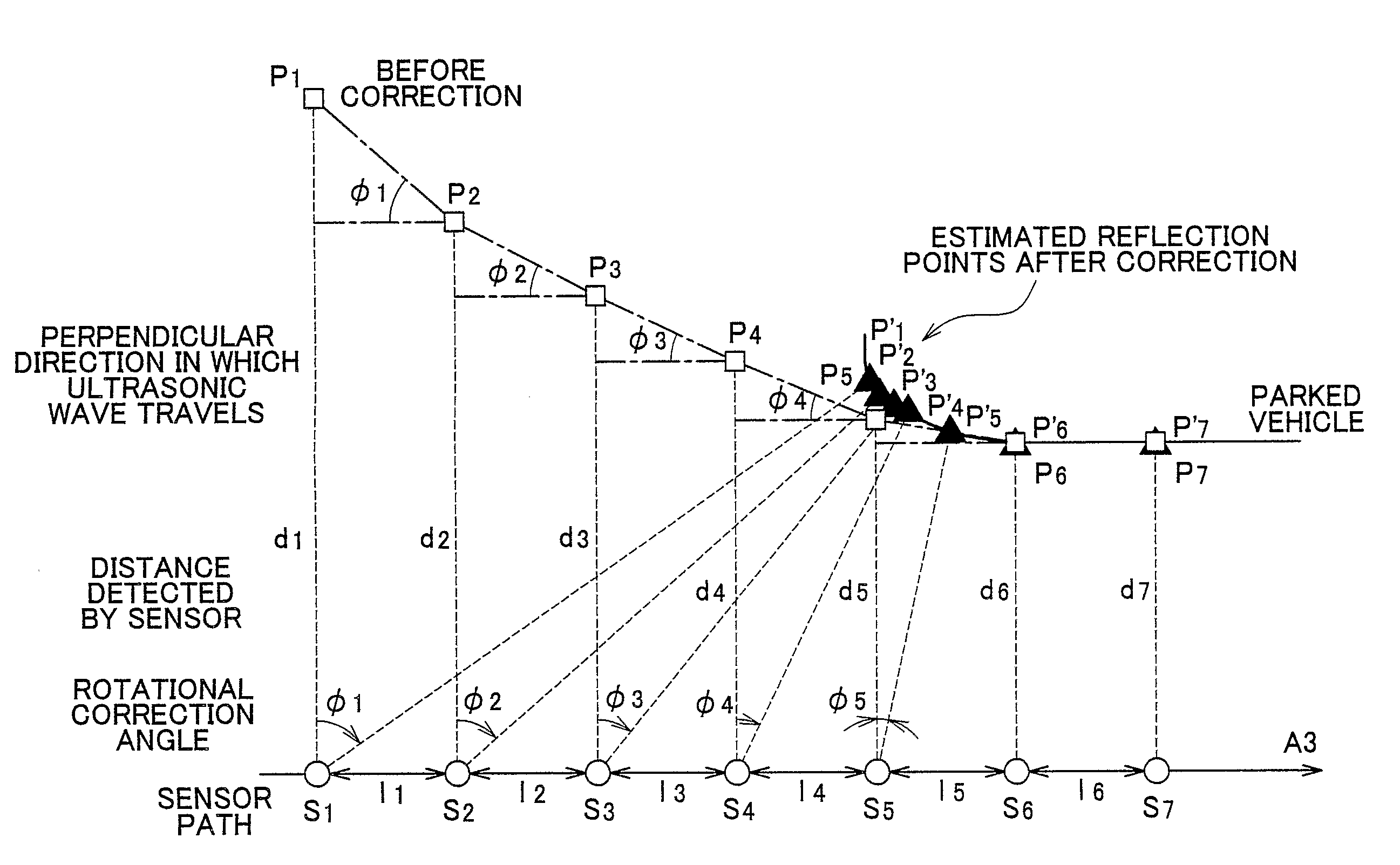
[0052]Detailed description will be given below of preferred embodiments of the invention with reference to the drawings. The same or corresponding portions are denoted by the same reference numerals in the drawings. In this description, an object detection apparatus of the embodiment will be explained by taking, as an example, a case where the invention is applied to a parking assist system for assisting the movement of a vehicle to a preset, desired parking position by automatic steering or by steering assist.

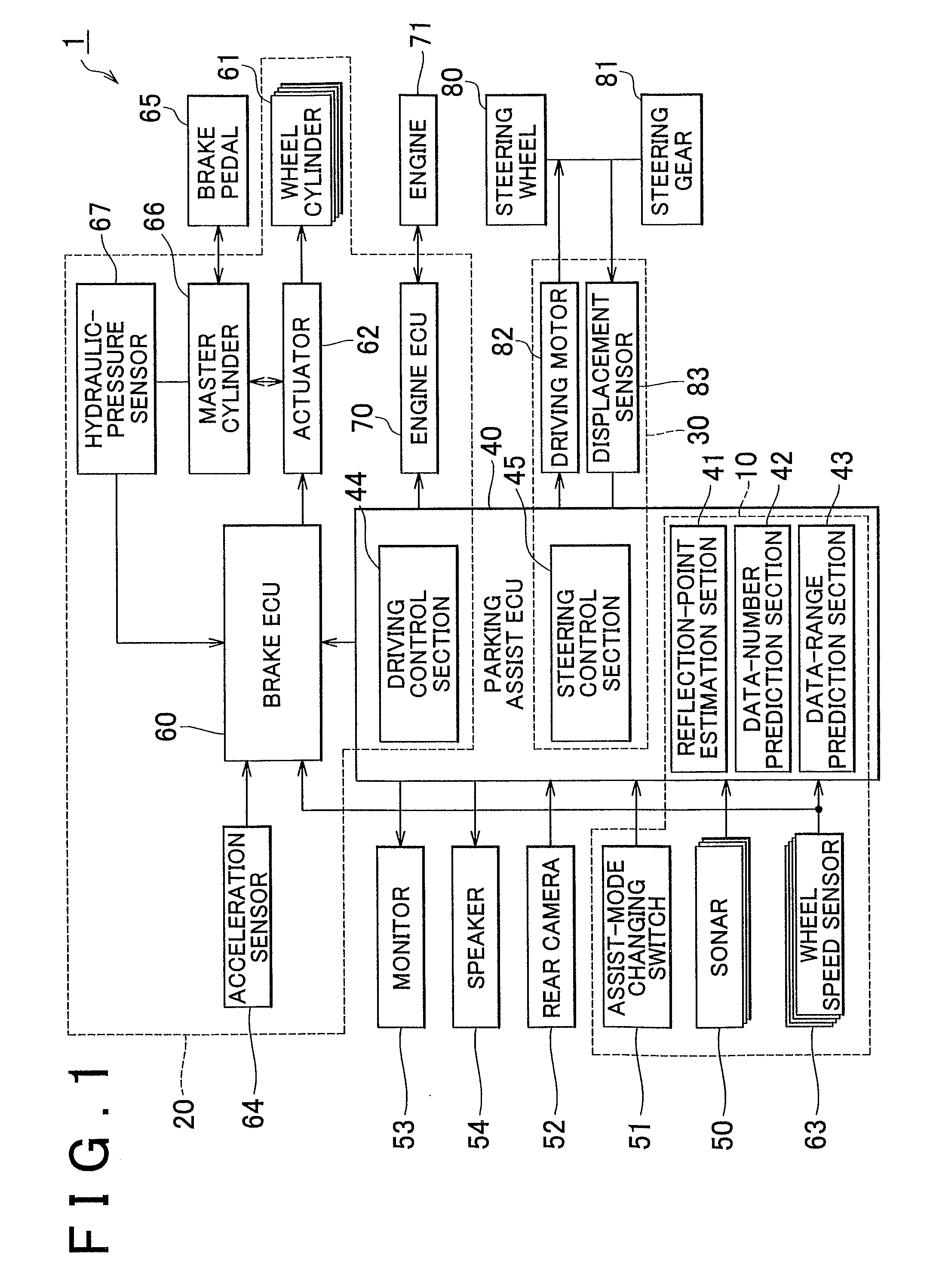
[0053]First of all, description will be given of a configuration of a parking assist system 1 including the object detection apparatus 10 of the embodiment with reference to FIG. 1. FIG. 1 is a block diagram showing the configuration of the parking assist system 1 including the object detection apparatus 10.

[0054]The parking assist system 1 assists the operation to park in a garage or the operation to perform parallel parking by using the image of a rear area of the vehicle, w...


PUM


Abstract

A reflection-point estimation section constituting an object detection apparatus first calculates a rotational correction angle for each estimated reflection point Pn by using the following equation, using the fact that the ratio of the amount of change in a detected distance dn to a movement amount In of a sonar is nearly equal to a tangent with respect to the direction normal to the surface of an object:Rotational correction angleφ=atan{(dn+1−dn) / In}in which n is a natural number. Subsequently, the reflection-point estimation section obtains estimated reflection points Pn′ after correction, by rotating each estimated reflection point Pn based on the calculation result.

Description

BACKGROUND OF THE INVENTION[0001]1. Field of the Invention[0002]The invention relates to an object detection apparatus and an object detection method.[0003]2. Description of Related Art[0004]A technology for, when parking assist is performed, detecting an area in which a vehicle can be parked by detecting the distance from a parked vehicle, from a pole and the like, for example, via an ultrasonic sensor while moving, has been proposed. In general, ultrasonic sensors have a low directivity, and have a characteristic that its detection range extends with a substantially elliptical shape. For this reason, when an ultrasonic sensor detects the distances from obstacles, such as parked vehicles and poles, while moving along the obstacles, the ultrasonic sensor detects an obstacle before the ultrasonic sensor reaches the obstacle. In addition, the ultrasonic sensor still detects the obstacle after the ultrasonic sensor passes the obstacle, as long as the obstacle is within the elliptical d...

Claims


Application Information

Patent Timeline
Patent Type & Authority Applications(United States)
IPC IPC(8): G01S15/93G01S15/86G01S15/931
CPCG01S7/52004G01S15/025G01S15/931G01S2015/934G01S2013/9353G01S2015/935G01S2015/936G01S2013/9314G01S15/86G01S2013/932
Inventor HAYASAKA, SHOICHIOKUDA, MASATOSATONAKA, HISASHI
Owner TOYOTA JIDOSHA KK
Why Eureka
Try Eureka