
Device and method for supporting the verification of a security document by means of a touchscreen

Inactive Publication Date: 2019-11-21
ORELL FJUSSLI ZIKHERKHAJTSDRUK AG
View PDF0 Cites 0 Cited by
  • Summary
  • Abstract
  • Description
  • Claims
  • Application Information

AI Technical Summary

Benefits of technology

The patent text describes how to make the verification process easier by developing a conductive structure that extends around at least half of the interaction region, allowing for more accurate position and orientation information. Additionally, the touchscreen can expand or animate the first part of the image on the document, making it easier to verify the authenticity of the document. This technology can enhance the security and accuracy of the verification process.

Problems solved by technology

Hence, the problem to be solved is to provide a method and device of the type mentioned above that can be used in the verification of a security document.

Method used


Image

  • Device and method for supporting the verification of a security document by means of a touchscreen
  • Device and method for supporting the verification of a security document by means of a touchscreen
  • Device and method for supporting the verification of a security document by means of a touchscreen

Examples


first embodiment

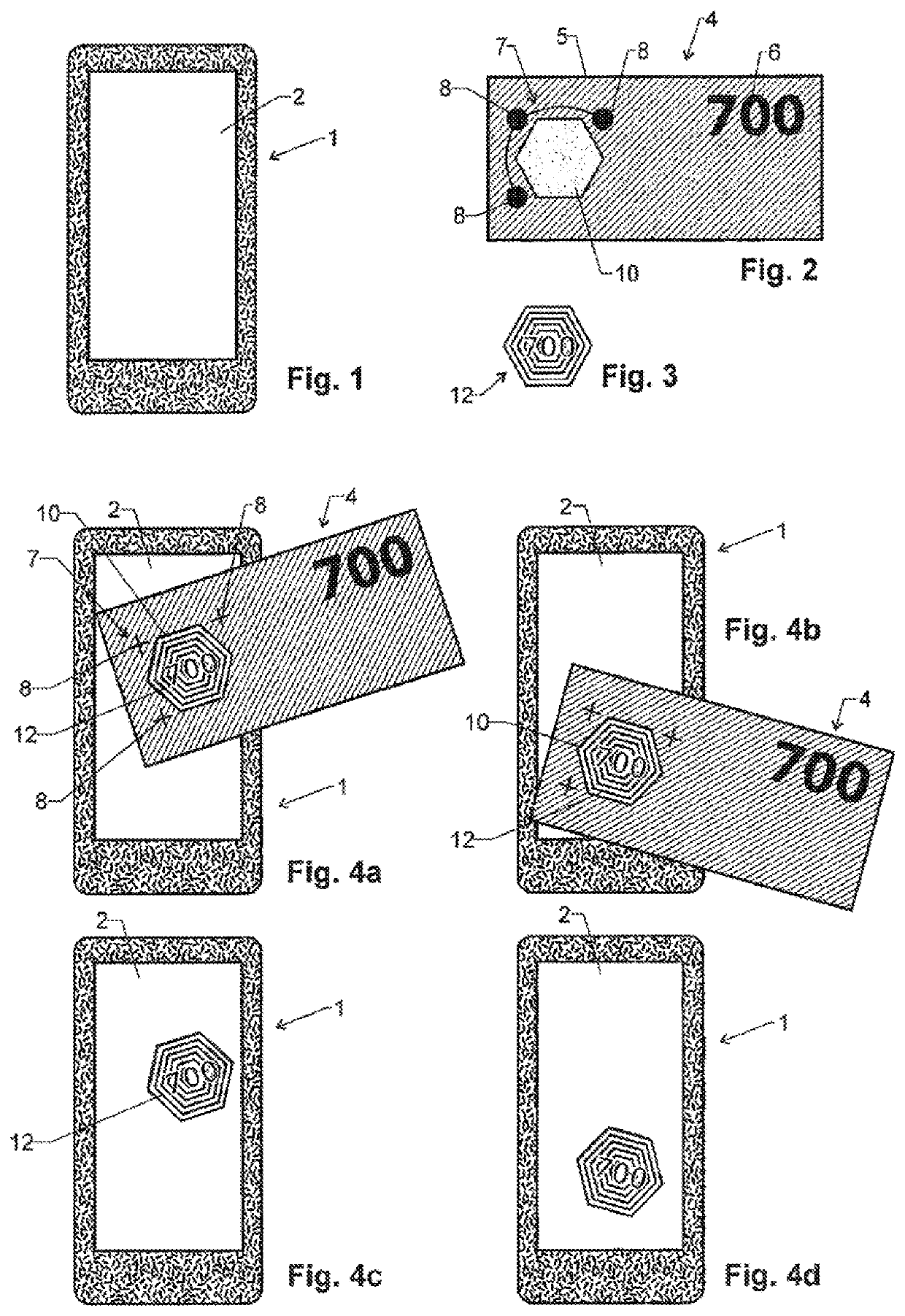
[0073]FIGS. 3 and 4a-4d illustrate a first embodiment of the invention to be used in combination with the security document of FIG. 2.

[0074]In this first embodiment, verification device 1 checks for the presence of security document 4 thereon by continuously scanning for the presence of a touch pattern corresponding to conductive structure 7.

[0075]If verification device 1 is adapted to cooperate with several types of security documents, the various types of documents can be equipped with differently configured conductive structures 7, and verification device 1 can be adapted to distinguish the types by analyzing the conductive structures 7.

[0076]Once that verification device 1 has detected the presence of security document 4 thereon, it will calculate its position, side and orientation as a function of the position and orientation of the detected conductive structure 7.

[0077]Then, verification device 1 will display an image on its touchscreen 2. The position and / or orientation of th...

second embodiment

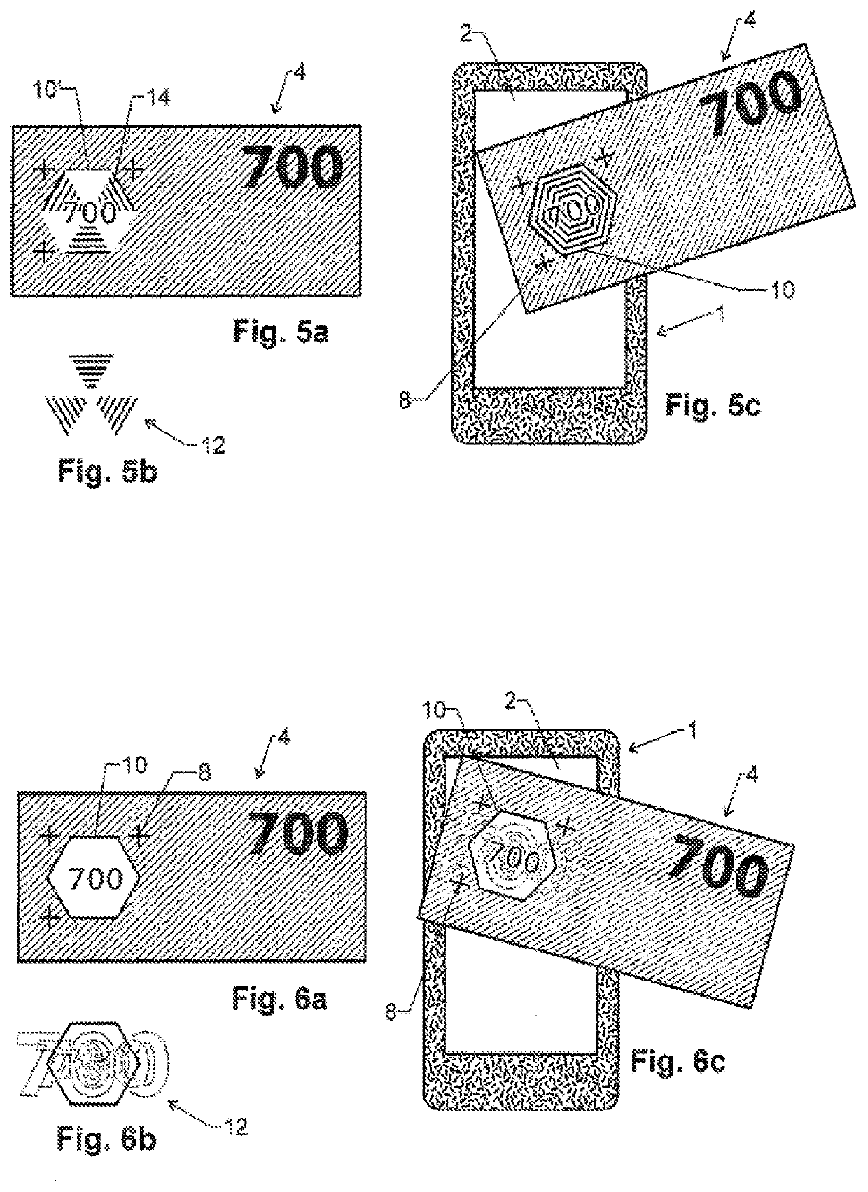
[0083]A second embodiment is shown in FIGS. 5a, 5b, 5c. In this embodiment, window 10 of security document 4 carries a pattern 14, which consists of a first part of the image shown in FIG. 3, i.e. half of the lines as well as the denomination.

[0084]The image 12 to be displayed by verification device 1 at the location of window 10 is shown in FIG. 5b. It consists of the second part of the image shown in FIG. 3, i.e. it consists of the other half of the lines.

[0085]When security document 4 is placed on verification device 1, the verification device will calculate the position and orientation of window 10 and then display image 12 therein, such that the complete image of FIG. 3 is recreated when viewing touchscreen 2 through window 10.

third embodiment

[0086]A third embodiment is shown in FIGS. 6a-6c. In this case, the image 12 is animated while being displayed on touchscreen 2. As schematically illustrated in FIG. 6b, the animation can e.g. comprise a periodic enlarging and shrinking of the denomination value 700, even though other types of animations can be used as well, e.g. rotation or color variation as well as, for example, short animated sequences of cartoons or videos.

[0087]In contrast to the embodiment of FIG. 4, where animation is used to make image 12 follow any motion of security document 4, in this embodiment animation takes places while document 4 is at rest.


PUM


Abstract

In order to support the verification of a security document, the document is placed on a verification device having a touchscreen. A conductive structure embedded in the document is detected by the touchscreen and the position and orientation of a window in the document is calculated therefrom. The verification device then displays an image positioned and rotated to appear at the location of the window. The image may interact with the document to generate Moiré patterns, fluorescent images or animations.

Description

TECHNICAL FIELD[0001]The invention relates to a method and device for supporting the verification of a security document.BACKGROUND ART[0002]Various methods and devices for supporting the verification of a security documents are known. For example, short-wavelength lamps can be used for exciting fluorescent inks on the security document, or detectors can be provided for detecting non-visible features such as magnetic or infrared-absorbing inks.[0003]The ongoing fight against new methods of counterfeiting provides a constant need for new methods and devices that support the verification of security documents.DISCLOSURE OF THE INVENTION[0004]Hence, the problem to be solved is to provide a method and device of the type mentioned above that can be used in the verification of a security document.[0005]This problem is solved by the independent claims.[0006]Accordingly, a method for supporting the verification of a security document is provided, which e.g. helps a human user or a machine t...

Claims


Application Information

Patent Timeline
IPC IPC(8): G07D7/128G06F3/044G06F3/14G07D7/1205G07D7/207G06K7/10
CPCB42D25/378G06F3/14G07D7/128G07D7/207G06K7/10366B42D25/351G07D2207/00G06F3/044G06F3/16B42D25/373G07D7/1205G06Q20/3221
Inventor CHOSSON, SYLVAINEICHENBERGER, MARTIN
Owner ORELL FJUSSLI ZIKHERKHAJTSDRUK AG
Learn More