Remaining amount detection sensor and ink-jet printer using the same

a technology of ink-jet printer and detection sensor, which is applied in the direction of liquid/fluent solid measurement, machines/engines, instruments, etc., can solve the problems of large change in capacitance of the ink tank due to the change in the remaining amount of ink to be detected, measurement error or erroneous detection, etc., and achieve high accuracy and blockage effect of capacitance of the detection electrode from the side and the rear side thereo

Inactive Publication Date: 2010-09-21
SII PRINTEK
View PDF7 Cites 20 Cited by
  • Summary
  • Abstract
  • Description
  • Claims
  • Application Information

AI Technical Summary

Benefits of technology

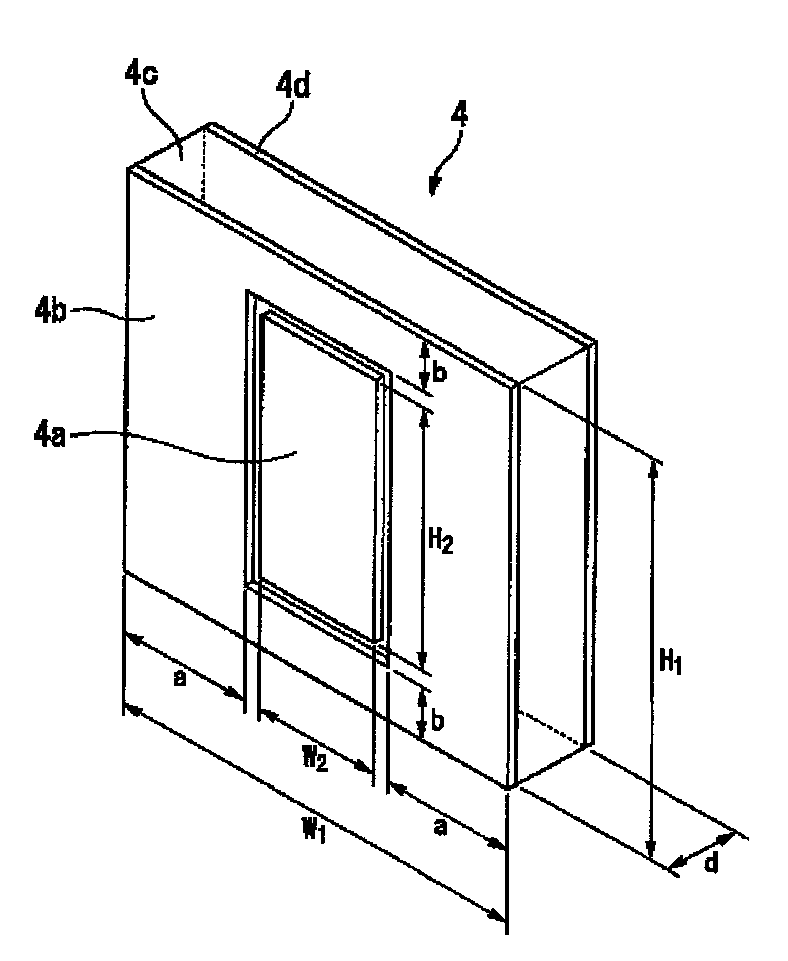
[0013]In the first aspect of the present invention, the detection electrode is disposed so as to face the container. Further, the first guard electrode surrounds the outer periphery of the detection electrode. The second guard electrode, which has the same potential as that of the first guard electrode, is disposed so as to face the detection electrode with a space in at least the range covering the detection electrode. As a result, effects of the arrangement of the components on a side of the detection electrode and on a rear side at which the second guard electrode is positioned, and of an external electric field, on the capacitance of the detection electrode can be blocked or reduced. Accordingly, the capacitance of the container, which is positioned near the surface of the detection electrode, and the capacitance of the content of the container can be detected with high accuracy.
[0033]In the remaining amount detection sensor according to the present invention and the ink-jet printer using the same, the effects on the capacitance of the detection electrode from the side and the rear side thereof can be blocked or reduced. As a result, it is possible to obtain an effect in that the remaining amount of the content of the container, which the detection electrode faces, can be detected with high accuracy.

Problems solved by technology

For example, JP 08-197749A discloses an ink-jet printer which includes an ink tank for storing conductive ink, electrodes for outside of the container, and the two detection electrodes sandwiching the container are affected by other conductive structures and electrical circuits disposed on the periphery of the detection circuit, so there arises a problem in that the capacitance is changed due to a change in surrounding environments and the like, and a measurement error or erroneous detection occurs.
In particular, in the case of the ink-jet printer, the change in capacitance of the ink tank due to the change in remaining amount of the ink to be detected is generally extremely small.
Accordingly, the noise due to the external factors has a large effect on the measurement accuracy.
As a result, an amount of noise to be generated due to the external factors is increased.
For this reason, the capacitance is formed also between detection electrodes of another adjacent remaining amount detection sensor, which causes an increase in measurement error.
In order to eliminate the effects of the surrounding environments, the remaining amount detection sensor and the ink tanks can be disposed to be spaced apart from other members and other remaining amount detection sensors which affect the capacitance, but there arises another problem in that the apparatus is increased in size.

Method used


Image

  • Remaining amount detection sensor and ink-jet printer using the same
  • Remaining amount detection sensor and ink-jet printer using the same
  • Remaining amount detection sensor and ink-jet printer using the same

Examples


first embodiment

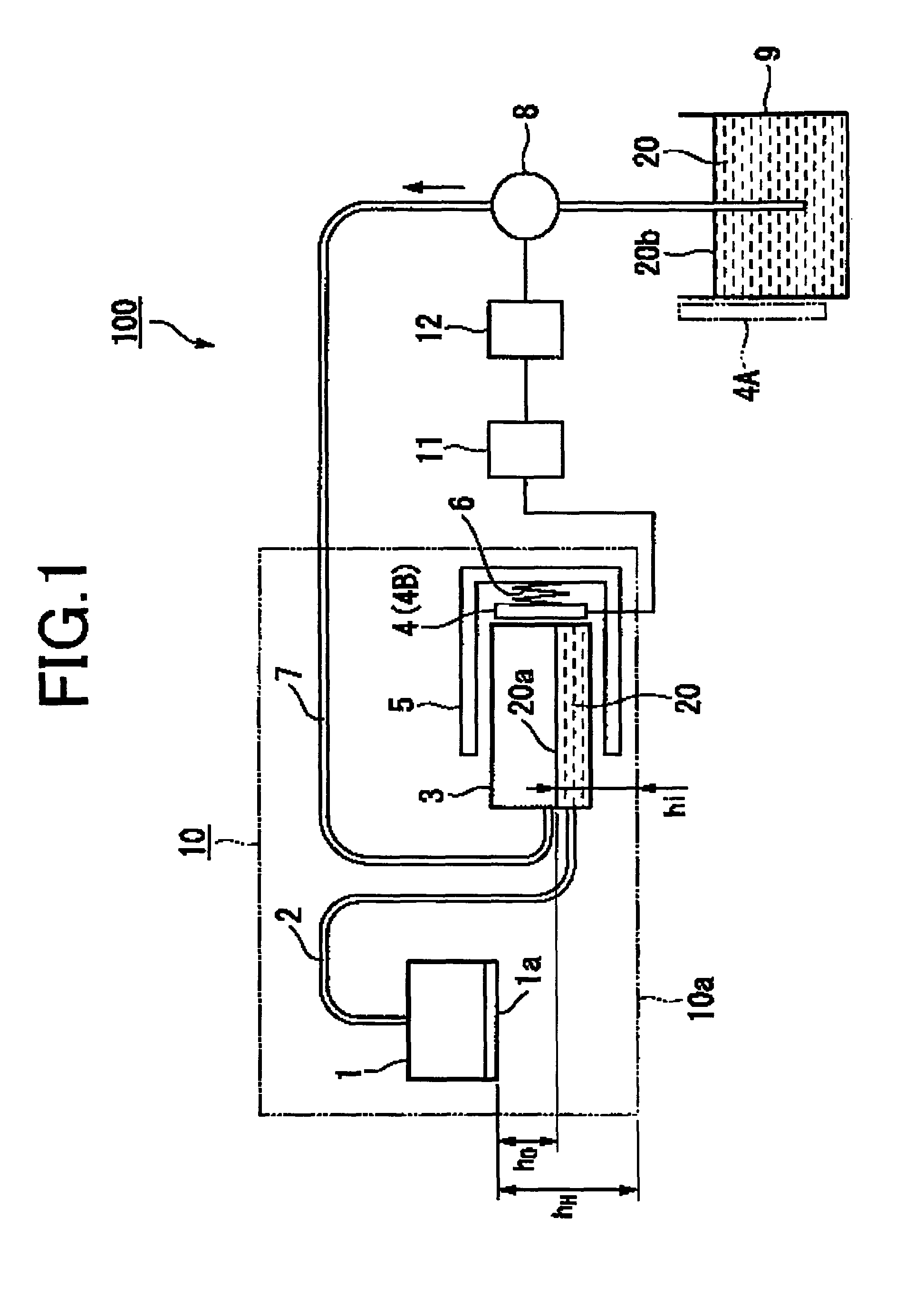
[0057]A description is given of a remaining amount detection sensor according to a first embodiment of the present invention as well as an ink-jet printer using the same.

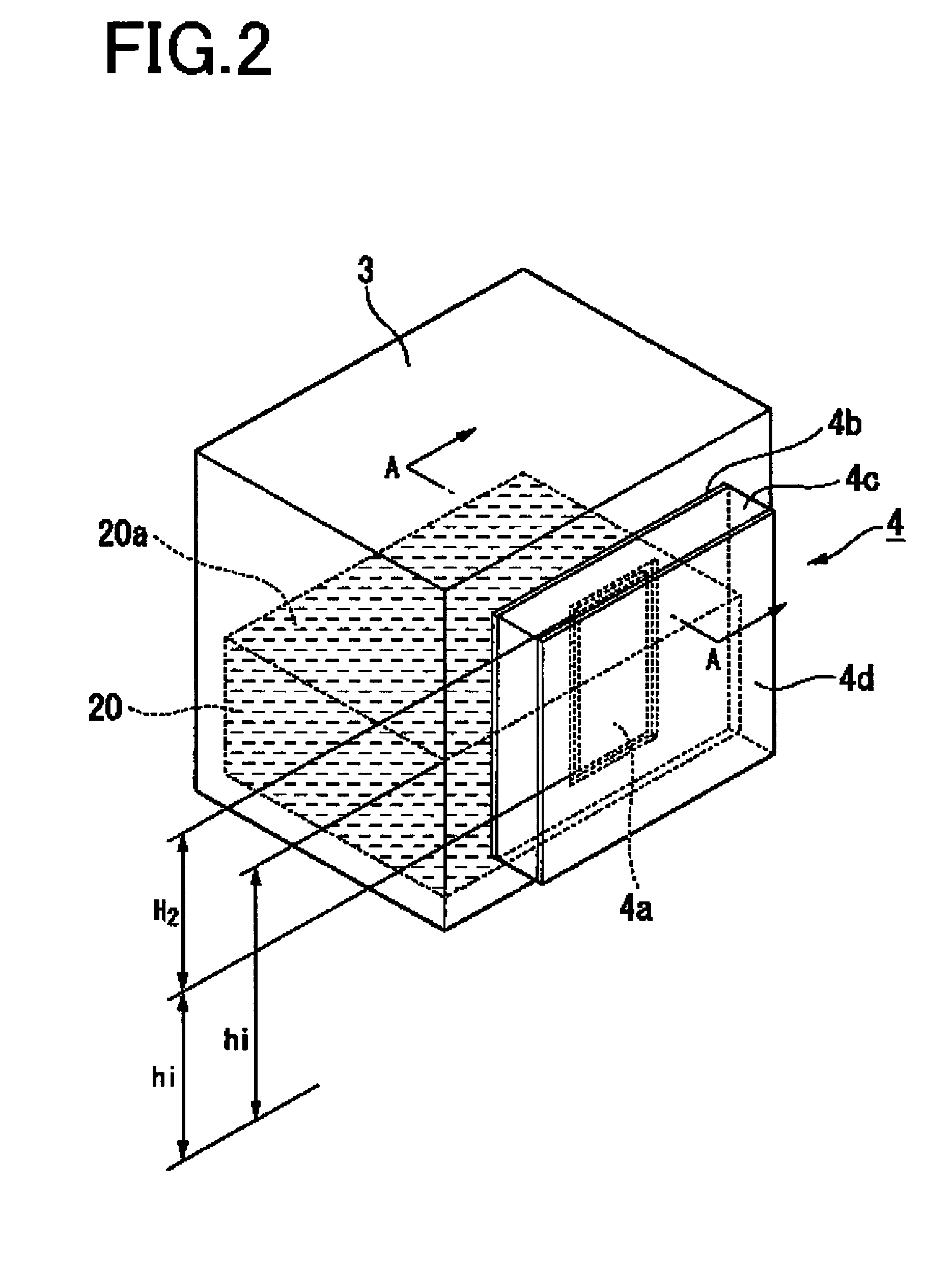
[0058]FIG. 1 is an explanatory block diagram schematically showing a general structure of the ink-jet printer using the remaining amount detection sensor according to the first embodiment of the present invention. FIG. 2 is a perspective view showing an arrangement state of the remaining amount detection sensor according to the first embodiment of the present invention. FIG. 3 is a perspective view showing a structure of the remaining amount detection sensor according to the first embodiment of the present invention. FIG. 4 is a cross-sectional diagram of the remaining amount detection sensor according to the first embodiment of the present invention taken along the line A-A of FIG. 2. FIG. 5 is a circuit diagram showing an example of a remaining amount detection circuit for taking out an output voltage from the rem...

second embodiment

[0101]A description is given of a remaining amount detection sensor according to a second embodiment of the present invention.

[0102]FIG. 8 is a perspective view showing a structure of the remaining amount detection sensor according to the second embodiment of the present invention. FIG. 9 is a cross-sectional diagram of a side view of an arrangement state of the remaining amount detection sensor according to the second embodiment of the present invention. FIGS. 10A and 10B are graphs each schematically showing a relation between a liquid level position in a container and a capacitance of a detection electrode of the remaining amount detection sensor according to the second embodiment of the present invention. An axis of abscissa represents the liquid level position and an axis of ordinate represents the capacitance to be detected.

[0103]As shown in FIGS. 8 and 9, a remaining amount detection sensor 4A according to the second embodiment of the present invention includes detection elec...

third embodiment

[0120]A description is given of a remaining amount detection sensor according to a third embodiment of the present invention.

[0121]FIG. 11 is an exploded perspective view showing arrangement of electrodes of the remaining amount detection sensor according to the third embodiment of the present invention. FIG. 12 is a cross-sectional diagram of a side view of a structure of the remaining amount detection sensor according to the third embodiment of the present invention.

[0122]As shown in FIGS. 11 and 12, a remaining amount detection sensor 4B according to the third embodiment of the present invention includes a guard electrode 41e (third guard electrode), a reference electrode 41a, and a dielectric layer 41b, in addition to a detection part 41A which is structured in the same manner as the remaining amount detection sensor 4 of the first embodiment.

[0123]The guard electrode 41e is a conductive layer having the same shape and made of the same material as the guard electrode 4d, is disp...


PUM


Abstract

Provided is a remaining amount detection sensor (4) which is disposed outside a sub-tank (3) to detect a remaining amount of an ink (20), including: a detection electrode (4a) disposed so as to face the sub-tank (3); a guard electrode (4b) disposed in the same plane as the detection electrode (4a) so as to surround an outer periphery of the detection electrode (4a); and a guard electrode (4d) which is disposed so as to face the detection electrode (4a) with a space in at least a range covering the detection electrode (4a), and has the same potential as that of the guard electrode (4b), in which the remaining amount of the content of the sub-tank (3) can be detected based on a capacitance to be measured by the detection electrode (4a) with the potentials of the guard electrodes (4b) (4d) each being set as a reference potential. Accordingly, in the remaining amount detection sensor and the ink-jet printer using the same, the remaining amount of the content of the container can be detected with high accuracy.

Description

BACKGROUND OF THE INVENTION[0001]1. Field of the Invention[0002]The present invention relates to a remaining amount detection sensor for detecting a remaining amount of content of a container, and an ink-jet printer using the same.[0003]2. Description of the Related Art[0004]Up to now, there have been known various remaining amount detection sensors for detecting a remaining amount of content, such as liquid and powder, contained in a container.[0005]For example, in an ink-jet printer for performing image recording and the like by discharging ink from an ink-jet head, a remaining amount of ink contained in an ink tank for supplying ink to the ink-jet head is monitored. Then, when the ink remaining amount decreases, ink is replenished from an ink replenishment tank, and in a case where the ink tank is a replaceable cartridge, it is notified that a time for replacement of the ink tank approaches. Further, there has been known that a remaining amount detection sensor of a capacitance t...

Claims


Application Information

Patent Timeline
Patent Type & Authority Patents(United States)
IPC IPC(8): B41J2/195B41J2/30B41J29/393B41J2/175G01F23/00
CPCB41J2/17509B41J2/17566B41J2002/17579
Inventor WATANABE, TOSHIAKI
Owner SII PRINTEK
Why Eureka
Try Eureka