Remaining amount detection sensor and ink-jet printer using the same
Inactive Publication Date: 2009-02-12
SII PRINTEK
5 Cites 31 Cited by
AI-Extracted Technical Summary
Problems solved by technology
For example, JP 08-197749A discloses an ink-jet printer which includes an ink tank for storing conductive ink, electrodes for outside of the container, and the two detection electrodes sandwiching the container are affected by other conductive structures and electrical circuits disposed on the periphery of the detection circuit, so there arises a problem in that the capacitance is changed due to a change in surrounding environments and the like, and a measurement error or erroneous detection occurs.
In particular, in the case of the ink-jet printer, the change in capacitance of the ink tank due to the change in remaining amount of the ink to be detected is generally extremely small.
A...
View moreMethod used
[0132]In this case, because the reference part 41B is integrated with the detection part 41A and is made of the same material as that of the detection part 41A, the reference part 41B is to be changed in the same manner as the detection part 41A when the capacitance is changed due to a change in environmental conditions, for example, a change in temperature and humidity. As a result, even when the environmental conditions are changed, the difference ΔC in capacitance between the detection part 41A and the reference part 41B is obtained in a state where effects of the environmental conditions are cancelled, and the difference ΔC can be measured with high accuracy.
[0138]In the remaining amount detection sensor 4C according to the modified example, the remaining amount detection circuit part 43 is adjacent to and integrated with the sensor part 42. As a result, the wiring from each of the detection electrode 4a and the reference electrode 41a to the remaining amount detection circuit part 43 can be shortened and can be easily shielded by the use of the wiring pattern of the multilayer board, and signal degradation and noise contamination via the wiring can be reduced.
[0163]Further, since the guard electrode 44d and the reference electrode 44e are formed in the same plane, in the case of forming the detection electrode 4a, the guard electrodes 44b, 44d, and 41e, and the reference electrode 44e by the conductive pattern of the multilayer printed board, the guard electrode 44d and the reference electrode 44e are formed by the conductive pattern in the same layer. As a result, the number of layers of the multilayer printed board can be reduced.
[0164]In order to reduce the effects of the environmental conditions on the remaining amount detection accuracy of the remaining amount detection sensor 4D, it is preferable that the detection part 44A and the reference part 44B be disposed under substantially the same environmental conditions.
[0171]Specifically, as shown in FIG. 17, in the remaining amount detection sensor 4E according to the fifth embodiment of the present invention, the detection electrode 4a and the guard electrodes 44b, 44d, 44e, and 41e of the sensor part 45A are formed by first to third layer conductive patterns of the four-layered printed board, and a fourth layer conductive pattern 45h is used for printed wiring for forming the detection circuit part 45B. A circuit part 45i is mounted in the conductive pattern 45h, and a side of the sensor part 45A and a si...
View moreBenefits of technology
[0033]In the remaining amount detection sensor according to the present invention and the ink-jet printer using the same, the effects on the capacitance of the detection electrode from the side and the rear side th...
View moreAbstract
Provided is a remaining amount detection sensor (4) which is disposed outside a sub-tank (3) to detect a remaining amount of an ink (20), including: a detection electrode (4a) disposed so as to face the sub-tank (3); a guard electrode (4b) disposed in the same plane as the detection electrode (4a) so as to surround an outer periphery of the detection electrode (4a); and a guard electrode (4d) which is disposed so as to face the detection electrode (4a) with a space in at least a range covering the detection electrode (4a), and has the same potential as that of the guard electrode (4b), in which the remaining amount of the content of the sub-tank (3) can be detected based on a capacitance to be measured by the detection electrode (4a) with the potentials of the guard electrodes (4b) (4d) each being set as a reference potential. Accordingly, in the remaining amount detection sensor and the ink-jet printer using the same, the remaining amount of the content of the container can be detected with high accuracy.
Application Domain
Technology Topic
Image
Examples
- Experimental program(8)
Example
First Embodiment
[0057]A description is given of a remaining amount detection sensor according to a first embodiment of the present invention as well as an ink-jet printer using the same.
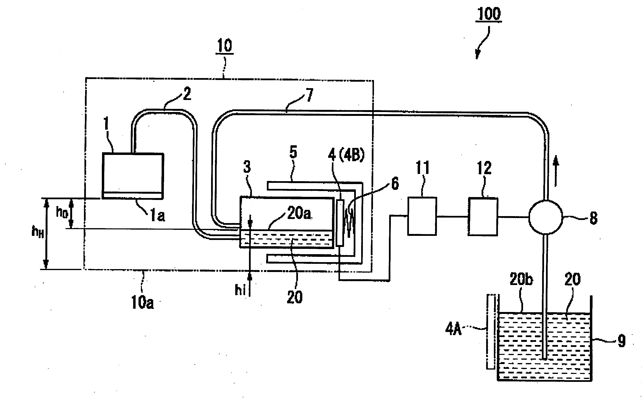
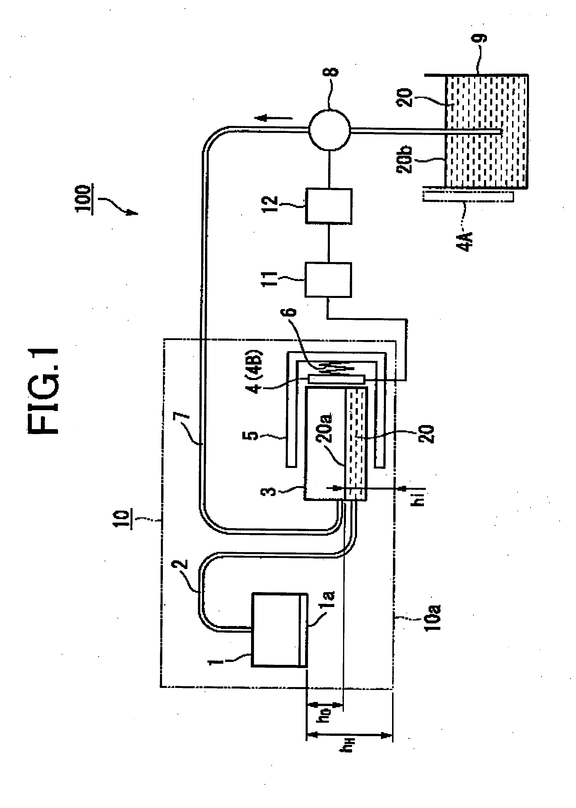
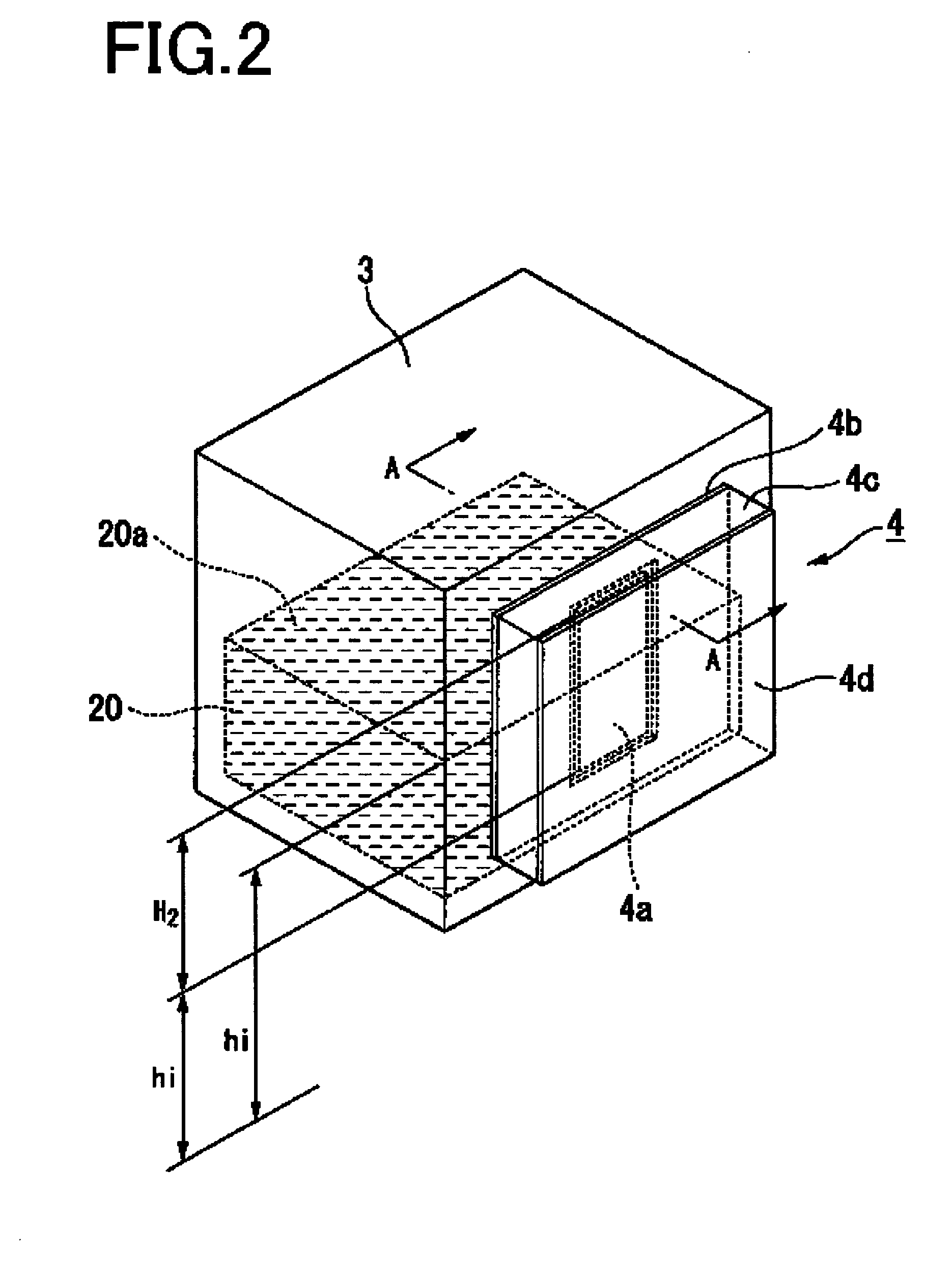
[0058]FIG. 1 is an explanatory block diagram schematically showing a general structure of the ink-jet printer using the remaining amount detection sensor according to the first embodiment of the present invention. FIG. 2 is a perspective view showing an arrangement state of the remaining amount detection sensor according to the first embodiment of the present invention. FIG. 3 is a perspective view showing a structure of the remaining amount detection sensor according to the first embodiment of the present invention. FIG. 4 is a cross-sectional diagram of the remaining amount detection sensor according to the first embodiment of the present invention taken along the line A-A of FIG. 2. FIG. 5 is a circuit diagram showing an example of a remaining amount detection circuit for taking out an output voltage from the remaining amount detection sensor according to the first embodiment of the present invention.
[0059]As shown in FIG. 1, an ink-jet printer 100 according to the first embodiment of the present invention includes an ink-jet head 1, a sub-tank 3 (ink tank), a sensor holder 5, a remaining amount detection sensor 4, which are accommodated in a carriage 10 held so as to be relatively movable with respect to a surface of a recording medium (not shown), and a main tank 9 for supplying an ink 20 to the sub-tank 3. The ink-jet printer 100 performs image recording and the like by discharging ink droplets toward the recording medium.
[0060]The ink-jet head 1 discharges ink droplets toward the recording medium from a head surface 1a on which a plurality of ink nozzles are arranged, and includes, inside thereof, known structures (not shown) such as an ink chamber and an ink discharge mechanism using a piezoelectric element.
[0061]The ink-jet head 1 is connected to the sub-tank 3 through an ink tube 2 so as to be supplied with the ink 20 from the sub-tank 3.
[0062]The ink-jet head 1 is fixed at a position of a height hH from a bottom surface 10a which is a reference surface of the carriage 10 in a height direction thereof.
[0063]The sub-tank 3 is a container for storing a certain amount of the ink 20 as the content so as to supply the ink 20 to the ink-jet head 1 from a position near the ink-jet head 1. For example, there can be employed a sub-tank having a rectangular parallelepiped outer shape made of polyethylene resin or the like with a thickness of 1 mm.
[0064]To an upper side of the sub-tank 3 an ink tube 7 for introducing the ink 20 from the main tank 9 is connected, and to a lower side thereof, the ink tube 2 for supplying the stored ink 20 to the ink-jet head 1 is connected.
[0065]The sub-tank 3 is detachably held by the sensor holder 5 which is fixed at a predetermined position in the carriage 10, and is fixed to be positioned with respect to the sensor holder 5 when the sub-tank 3 is mounted thereto.
[0066]Note that, for ease of explanation, a single sub-tank 3 is illustrated in the following description and the drawings. However, in a case of performing color printing, a plurality of sub-tanks 3 having the same structure are arranged in parallel with each other according to the number of colors of the ink 20.
[0067]The sensor holder 5 is a holding member for detachably fixing the sub-tank 3 and for performing positioning of the sub-tank 3 in the carriage 10. Inside the sensor holder 5, there is provided the remaining amount detection sensor 4 which is urged by a pressure spring 6 to be brought into close contact with a side surface of the sub-tank 3 being mounted.
[0068]A height of the sensor holder 5 being mounted is set so that a given meniscus shape is formed at the ink nozzles formed on the head surface 1a and an ink liquid level 20a in the sub-tank 3 is lower than the head surface 1a. In other words, a height hi of a bottom surface 10a, which is measured from the bottom surface 10a of the carriage 10, is represented as hi H.
[0069]As shown in FIG. 2, the remaining amount detection sensor 4 is disposed outside the side surface of the sub-tank 3, and detects the height of the ink liquid level 20a by measuring a capacitance on a side of the sub-tank 3, thereby detecting the remaining amount of the ink 20 contained in the sub-tank 3.
[0070]As shown in FIGS. 2 to 4, the remaining amount detection sensor 4 has a structure in which an electrode pattern which is formed of a detection electrode 4a and a guard electrode 4b (first guard electrode), and a guard electrode 4d (second guard electrode) are disposed so as to face each other through a dielectric layer 4c with a thickness d. The remaining amount detection sensor 4 has a rectangular outer shape with a size of W1×H1 which can be contained within a range of the side surface of the sub-tank 3.
[0071]The remaining amount detection sensor 4 according to the first embodiment of the present invention is structured by using a double-sided printed board. In other words, a conductive pattern is formed on one substrate surface as the electrode pattern formed of the detection electrode 4a and the guard electrode 4b, and the guard electrode 4d is formed on the other substrate surface as a solid pattern. In addition, a base material of the printed board forms the dielectric layer 4c. As a material of the double-sided printed board, for example, a glass composite substrate and a glass epoxy substrate can be employed.
[0072]The detection electrode 4a is provided at a substantial center of the surface on which a rectangular conductor layer with a long side H2 and a short side W2 (note that H2 1 and W2 1) is brought into close contact with the remaining amount detection sensor 4, thereby enabling detection of a potential via wiring (not shown). The long side of the detection electrode 4a is placed along a height direction of the sub-tank 3, that is, a vertical direction in which the ink liquid level 20a rises or falls.
[0073]The guard electrode 4b is a conductive layer which is disposed in the same plane as the detection electrode 4a so as to surround an outer periphery of the detection electrode 4a and which is extended to an outer edge of the remaining amount detection sensor 4, that is, the rectangular outer shape having the size of W1×H1, and is grounded via wiring (not shown).
[0074]The guard electrode 4d is a conductive layer which faces the detection electrode 4a and the guard electrode 4b and which covers the detection electrode 4a and the guard electrode 4b to be extended to the outer edge of the remaining amount detection sensor 4, and is grounded via wiring (not shown).
[0075]As a result, as shown in FIG. 4, between the detection electrode 4a and the guard electrode 4b, and between the detection electrode 4a and the guard electrode 4d, there are formed capacitors having a combined capacitance of CS.
[0076]As shown in FIG. 1, wiring connected to the detection electrode 4a and a ground wire connected to each of the guard electrodes 4b and 4d are electrically connected to a remaining amount detection circuit part 11 (remaining amount detection circuit) for detecting the capacitance of the detection electrode 4a to thereby detect the remaining amount in the sub-tank 3.
[0077]As long as a potential of the detection electrode 4a can be detected with a required accuracy, the remaining amount detection circuit part 11 may have any circuit configuration. In the first embodiment of the present invention, as an example, a AC-V conversion circuit as shown in FIG. 5 is employed.
[0078]The remaining amount detection circuit part 11 according to the first embodiment of the present invention outputs a voltage VOUT obtained by converting, into a voltage, a difference ΔC in capacitance of a reference capacitor 31 having the capacitance CS of the detection electrode 4a and a known capacitance Cref. The remaining amount detection circuit part 11 includes an oscillator 30 for adding sine-wave signals to the remaining amount detection sensor 4 and the reference capacitor 31, a differential amplifier 32 for detecting a difference between the signals, a rectifier 33 for rectifying an output of the differential amplifier 32, and an amplifier 34 for amplifying the signals rectified by the rectifier 33. As the differential amplifier 32, there can be employed a typical operational amplifier for comparing and calculating a voltage amplitude difference and a voltage phase difference, which are generated between both ends of the capacitance CS and the capacitance Cref, to output the difference.
[0079]In the remaining amount detection circuit part 11, the voltage VOUT corresponds to a phase difference amount which is generated according to the difference ΔC in capacitance between the detection electrode 4a and the reference capacitor 31. Accordingly, when CS=Cref is satisfied, VOUT=0 is established. A value of VOUT is used to calculate the difference ΔC, and the capacitance of the detection electrode 4a can be measured assuming that CS=Cref+ΔC.
[0080]In the first embodiment of the present invention, the capacitance Cref of the reference capacitor 31 is set to a value equal to a capacitance CS2 of the detection electrode 4a in a case where a position in the height direction with respect to the head surface 1a of the ink liquid level 20a in the sub-tank 3 matches an appropriate position L2 at which the given meniscus shape is formed at the ink nozzles of the ink-jet head 1.
[0081]The remaining amount detection circuit part 11 is electrically connected to a pump drive control part 12 for controlling a pump-up operation of a lift pump 8 connected to the ink tube 7, and the output voltage VOUT is sent to the pump drive control part 12.
[0082]The pump drive control part 12 can control driving, stopping, and a pump-up quantity of the lift pump 8 according to the position of the ink liquid level 20a to be detected based on the output voltage VOUT of the remaining amount detection circuit part 11.
[0083]For example, the pump drive control part 12 according to the first embodiment of the present invention performs the control in the following manner. When the output voltage VOUT is a negative value, that is, when the ink liquid level 20a is lower than the appropriate position L2, the pump drive control part 12 drives the lift pump 8, and when the output voltage VOUT is 0 or larger, that is, when the ink liquid level 20a reaches the appropriate position L2, the pump drive control part 12 stops the lift pump 8. Accordingly, when the ink-jet head 1 consumes the ink 20 to thereby lower the ink liquid level 20a, replenishment of the ink 20 is automatically performed, thereby constantly maintaining the ink liquid level 20a at the appropriate position L2.
[0084]The main tank 9 is a container for storing the ink 20 used for replenishing the ink 20, which is discharged from the ink-jet head 1 to be consumed, to the sub-tank 3, at a position apart from the carriage 10.
[0085]The ink 20 contained in the main tank 9 is pumped up by the lift pump 8 and is supplied to the sub-tank 3 through the ink tube 7.
[0086]Next, operations of the ink-jet printer 100 will be described mainly about a remaining amount detection operation of the remaining amount detection sensor 4.
[0087]FIG. 6 is a graph schematically showing a relation between the liquid level position in the container and the capacitance of the detection electrode of the remaining amount detection sensor according to the first embodiment of the present invention. An axis of abscissa represents the liquid level position and an axis of ordinate represents the capacitance to be detected. FIG. 7A is a conceptual diagram for explaining a range of the capacitance to be detected by the remaining amount detection sensor according to the embodiment of the present invention. FIG. 7B is a conceptual diagram for explaining a range of the capacitance to be detected by a remaining amount detection sensor according to a related art.
[0088]In the remaining amount detection sensor 4, the guard electrode 4b, which is grounded, is disposed around the detection electrode 4a, and the guard electrode 4d, which is grounded, is disposed in a range covering the guard electrode 4b so as to face each of the detection electrode 4a and the guard electrode 4b.
[0089]Accordingly, the capacitance of the detection electrode 4a on a side of the guard electrode 4d is constant, and an electric field outside the guard electrode 4d is shielded.
[0090]As a result, the capacitance of the detection electrode 4a is not affected even when, for example, a positional relation with respect to components provided outside the guard electrode 4d is changed by the movement of the carriage 10, other movable members, and the like. Further, even when an electrical circuit is provided near an external surface side of the guard electrode 4d, an effect of the electric field generated by the electrical circuit is blocked or reduced.
[0091]On the other hand, in a space formed on the sub-tank 3 side, the detection electrode 4a is adjacent to the guard electrode 4b through the sub-tank 3 and the ink 20 contained in the sub-tank 3.
[0092]For this reason, in the remaining amount detection sensor 4, the capacitance of the detection electrode 4a is affected only by a change of a dielectric body provided in the space formed on the sub-tank 3 side near the surface of the detection electrode 4a, as shown in a region P indicated by the alternate long and two short dashes line of FIG. 7A.
[0093]Accordingly, effects of various noises can be reduced, thereby making it possible to measure the capacitance near the detection electrode 4a with high accuracy.
[0094]For example, as in a comparative example of the related art shown in FIG. 7B, when a reference electrode 50b and a detection electrode 50a, which are grounded, are disposed in the height direction on the side surface of the sub-tank 3 to measure the capacitance CS of the detection electrode 50a, the capacitance of the detection electrode 50a is affected by peripheral dielectric bodies provided therearound in almost all the directions. Accordingly, as shown within a range of a region Q, the capacitance of the detection electrode 50a is affected also by the dielectric body provided outside the sub-tank 3 to the same degree as the sub-tank 3 and the dielectric body inside the sub-tank 3.
[0095]As a result, unlike the case of the first embodiment of the present invention, for example, when the positional relation with respect to the components provided outside the detection electrode 50a is changed by the movement of the carriage 10, other movable members, and the like, the capacitance of the detection electrode 50a is to be changed. In addition, the detection electrode 50a is affected also by the electric field of the electrical circuit disposed near the detection electrode 50a because the electric field outside the detection electrode 50a is not shielded.
[0096]As shown in FIG. 4, in the sub-tank 3, when the liquid level is changed from a height L1 to a height L3 (L3L1) substantially corresponding to a height range of the long side of the detection electrode 4a, the capacitance is increased according to the rise of the ink liquid level 20a. For example, as represented by a curve 200 shown in FIG. 6, while the ink liquid level 20a is changed from L1 to L2 to L3, the capacitance is substantially linearly and monotonously increased from CS1 to CS2 to and CS3.
[0097]As a specific numerical example, the range of the capacitance to be detected by the remaining amount detection sensor 4 is, for example, a range from CS1=28 pF to CS3=55 pF in the following case. That is, for example, in a case where there is used the remaining amount detection sensor 4 which includes the dielectric layer 4c made of resin-impregnated glass fiber of d=1 mm, has the detection electrode 4a and the guard electrodes 4b and 4d each formed of copper foil having a thickness of 35 μm, has an outer shape of W1×H1=50 mm×50 mm, and has the detection electrode 4a formed with a size of W2×H2=16 mm×38 mm at a central position thereof (that is, a=16 mm and b=5 mm in FIG. 3), and in a case where the sub-tank 3 is made of polyethylene having a wall thickness of 1 mm and contains aqueous ink.
[0098]The remaining amount detection sensor 4 according to the first embodiment of the present invention can detect, as the output voltage VOUT of the remaining amount detection circuit part 11, the change in capacitance of the detection electrode 4a, which corresponds to the height of the ink liquid level 20a. In addition, the remaining amount detection sensor 4 can perform control such that the pump drive control part 12 drives the lift pump 8 so that the output voltage VOUT becomes constant, and so that the height of the ink liquid level 20a in the sub-tank 3 is set to the appropriate position L2.
[0099]In this case, the amount of the ink 20 to be discharged from the ink-jet head 1 is extremely small, and the change in capacitance due to fluctuation of the ink liquid level 20b is also extremely small. However, in the first embodiment of the present invention, measurement noise can be reduced, with the result that a liquid level control can be performed with accuracy.
[0100]Accordingly, even when the ink 20 is consumed by the ink-jet head 1, the height of the ink liquid level 20a in the sub-tank 3 can be stably maintained at the appropriate position L2. As a result, a stable meniscus can be formed at the ink nozzles of the excellent ink-jet head 1 and excellent image recording can be performed.
Example
Second Embodiment
[0101]A description is given of a remaining amount detection sensor according to a second embodiment of the present invention.
[0102]FIG. 8 is a perspective view showing a structure of the remaining amount detection sensor according to the second embodiment of the present invention. FIG. 9 is a cross-sectional diagram of a side view of an arrangement state of the remaining amount detection sensor according to the second embodiment of the present invention. FIGS. 10A and 10B are graphs each schematically showing a relation between a liquid level position in a container and a capacitance of a detection electrode of the remaining amount detection sensor according to the second embodiment of the present invention. An axis of abscissa represents the liquid level position and an axis of ordinate represents the capacitance to be detected.
[0103]As shown in FIGS. 8 and 9, a remaining amount detection sensor 4A according to the second embodiment of the present invention includes detection electrodes 40a and 40b in place of the detection electrode 4a of the remaining amount detection sensor 4 of the first embodiment, and a guard electrode 40c (second guard electrode) in place of the guard electrode 4b.
[0104]As shown in FIG. 1, for example, the remaining amount detection sensor 4A is disposed outside the side surface of the main tank 9 in the ink-jet printer 100 of the first embodiment, and measures the capacitance on the main tank 9 side to detect whether a height of an ink liquid level 20b is within a predetermined range, thereby detecting the remaining amount of the ink 20 contained in the main tank 9.
[0105]Hereinafter, the differences from the first embodiment will be mainly described.
[0106]The detection electrodes 40a and 40b are rectangular conductive layers, each of which has a long side W3 and a short side H3, and which are arranged in parallel with each other with a distance H4 (note that 2·H3+H4 1 and W3 1) and are provided on a surface to be brought into close contact with the remaining amount detection sensor 4A, thereby enabling detection of a potential via wiring (not shown). The short side of each of the detection electrodes 40a and 40b is placed along a height direction of an object whose remaining amount is to be detected of, for example, the main tank 9, that is, a vertical direction in which the ink liquid level 20b rises or falls (see FIG. 9).
[0107]The guard electrode 40c is a conductive layer which is disposed in the same plane as the detection electrodes 40a and 40b so as to surround an outer periphery of each of the detection electrodes 40a and 40b, is extended to an outer edge of the remaining amount detection sensor 4A, that is, a rectangular outer shape with a size of W1×H1, and is grounded via wiring (not shown).
[0108]Accordingly, as shown in FIG. 9, between the detection electrodes 40a and 40b and the guard electrodes 40c and 4d, there are formed capacitors having combined capacitances Ca and Cb, respectively.
[0109]The capacitances Ca and Cb can be measured using an electrical circuit similar to the remaining amount detection circuit part 11 of the first embodiment.
[0110]The remaining amount detection sensor 4A with the above-mentioned structure has the same structure as that in which the remaining amount detection sensors 4 of the first embodiment are arranged in parallel with each other in a vertical direction to be integrated with each other.
[0111]Accordingly, in the same manner as in the detection electrode 4a of the first embodiment, the capacitance of the detection electrode 40a (40b) is affected only by the change of the dielectric body provided in the space formed on the sub-tank 3 side near the surface of the detection electrode 40a (40b) as shown in a region Pa (Pb) indicated by the alternate long and two short dashes line of FIG. 9.
[0112]Accordingly, when it is assumed that a height of the ink liquid level 20b near a lower end position of the detection electrode 40a and a height thereof near an upper end position of the detection electrode 40a are set as L1 and L2, respectively, and when it is assumed that a height of the ink liquid level 20b near a lower end position of the detection electrode 40b and a height thereof near an upper end position of the detection electrode 40b are set as L3 and L4, respectively, the capacitance of each of the detection electrodes 40a and 40b is changed as indicated by a curve 201 of FIG. 10A and a curve 202 of FIG. 10B.
[0113]Specifically, when the ink liquid level 20b is lower than the height L3, the capacitance of the detection electrode 40b is measured as a relatively small value Cb1 because the ink 20 does not enter the region Pb. When the ink liquid level 20b is positioned between the heights L3 and L4, the capacitance is substantially linearly increased from Cb1 to Cb2 according to the height of the ink liquid level 20b. When the ink liquid level 20b is equal to or higher than the height L4, the ink 20 is filled in the entire detection range of the detection electrode 40b, with the result that a constant value Cb2 is measured.
[0114]In a similar manner, when the height of the ink liquid level 20b is positioned between the heights L1 and L2, the capacitance of the detection electrode 40a is substantially linearly increased from Ca1 to Ca2, and when the height is equal to or higher than the height L2, a constant value Ca2 is measured.
[0115]Thus, according to the remaining amount detection sensor 4A, a magnitude of the capacitance of each of the detection electrodes 40b and 40a is analyzed, thereby making it possible to detect the positional relation of the ink liquid level 20b with respect to the four heights L1, L2, L3, and L4 corresponding to the arrangement positions of the detection electrodes 40b and 40a in the height direction. For example, when the capacitances of the detection electrodes 40b and 40a are Cb1 and Ca2, respectively, it can be detected that the ink liquid level 20b is positioned between the heights L2 and L3.
[0116]In particular, in a height range from L1 to L2, and in a height range from L3 to L4, by the use of the capacitance of each of the detection electrodes 40b and 40a, the height of the ink liquid level 20b can be measured.
[0117]In this case, in the same manner as in the first embodiment, the effects of various noises are reduced, thereby making it possible to measure the capacitances near the detection electrode 40a and 40b with high accuracy.
[0118]The remaining amount detection sensor 4A singly includes a plurality of detection electrodes. Accordingly, for example, the remaining amount detection sensor 4A can detect the ink liquid level 20b in the main tank 9, to thereby singly detect whether the remaining amount of the ink 20 contained in the main tank 9 is within the range of the predetermined amount with reliability. When the liquid level of the ink liquid level 20b is lower than the height L2, a reduction amount can be detected with accuracy. As a result, by the use of a detection output, an ink remaining amount can be displayed, and alarm display for urging a user to replenish ink can be performed.
[0119]Further, when the ink 20 is replenished to the main tank 9, through detection of the height of the ink liquid level 20b, a warning of proximity of a limit of a replenishment amount can be issued.
Example
Third Embodiment
[0120]A description is given of a remaining amount detection sensor according to a third embodiment of the present invention.
[0121]FIG. 11 is an exploded perspective view showing arrangement of electrodes of the remaining amount detection sensor according to the third embodiment of the present invention. FIG. 12 is a cross-sectional diagram of a side view of a structure of the remaining amount detection sensor according to the third embodiment of the present invention.
[0122]As shown in FIGS. 11 and 12, a remaining amount detection sensor 4B according to the third embodiment of the present invention includes a guard electrode 41e (third guard electrode), a reference electrode 41a, and a dielectric layer 41b, in addition to a detection part 41A which is structured in the same manner as the remaining amount detection sensor 4 of the first embodiment.
[0123]The guard electrode 41e is a conductive layer having the same shape and made of the same material as the guard electrode 4d, is disposed so as to face the guard electrode 4d on an opposite side of the detection electrode 4a, and is grounded via wiring (not shown).
[0124]Between the guard electrode 4d and the guard electrode 41e, the dielectric layer 41b made of the same material as that of the dielectric layer 4c is disposed.
[0125]The reference electrode 41a is formed of a conductive layer having an area smaller than that of each of the guard electrodes 4d and 41e, and is disposed in the dielectric layer 41b at an intermediate position in a direction in which the guard electrodes 4d and 41e are spaced apart, and at a substantial center between surface directions of the guard electrodes 4d and 41e, thereby making it possible to detect the potential via wiring (not shown).
[0126]The area of the reference electrode 41a, the distance between the guard electrodes 4d and 41e, and the like are set so that the capacitance of the reference electrode 41a is set to the constant value Cref.
[0127]Thus, in the remaining amount detection sensor 4B, the detection part 41A serving as a capacitor showing the capacitance CS corresponding to the peripheral dielectric body, and the reference part 41B serving as a capacitor having the constant capacitance Cref are integrated in layers.
[0128]Accordingly, the remaining amount detection sensor 4B according to the third embodiment of the present invention can be formed of a multilayer printed board with the detection electrode 4a, the guard electrode 4b, and the guard electrodes 4d and 41e each being used as the electrode pattern. In this case, the dielectric layer 41b is formed of a base material of the multilayer printed board.
[0129]In the remaining amount detection sensor 4B with the above-mentioned structure, the reference part 41B is integrated with the detection part 41A and serves as a capacitor made of the same material as that of the detection part 41A. Accordingly, the capacitance Cref can be formed in the same order as that of the capacitance CS of the detection part 41A merely by changing the area of the reference electrode 41a, the thickness of the dielectric layer 41b, and the like to a small extent in an analog manner.
[0130]For this reason, for example, it is extremely easy to obtain, through an experiment or the like, a capacitance in a case where the detection electrode 4a is disposed at a detection position of the sub-tank 3 and the ink liquid level 20a is positioned at the appropriate height, and to set the capacitance Cref to a value which exactly matches the measured value.
[0131]The reference part 41B thus set can be used in place of the reference capacitor 31 of the remaining amount detection circuit part 11 of the first embodiment.
[0132]In this case, because the reference part 41B is integrated with the detection part 41A and is made of the same material as that of the detection part 41A, the reference part 41B is to be changed in the same manner as the detection part 41A when the capacitance is changed due to a change in environmental conditions, for example, a change in temperature and humidity. As a result, even when the environmental conditions are changed, the difference ΔC in capacitance between the detection part 41A and the reference part 41B is obtained in a state where effects of the environmental conditions are cancelled, and the difference ΔC can be measured with high accuracy.
[0133]On the other hand, as in the first embodiment, in the case of using the reference capacitor 31 disposed at a position apart from the remaining amount detection sensor 4 and having a structure different from that of the remaining amount detection sensor 4, if the value of Cref can be set so as to be exactly matched with the value of CS in the appropriate condition, when the environmental conditions are changed, the remaining amount detection sensor 4 and the reference capacitor 31, which are made of different materials and have different structures, are individually changed in capacitance. As a result, a detection error of ΔC becomes larger than that in the case of using the remaining amount detection sensor 4B according to the third embodiment of the present invention.
[0134]Next, modified examples of the embodiments will be described.
[0135]FIG. 13 is a perspective view schematically showing a general structure of a remaining amount detection sensor according to a modified example of the third embodiment of the present invention.
[0136]In a remaining amount detection sensor 4C according to the modified example of the present invention, a sensor part 42 having the same structure as that of the remaining amount detection sensor 4B according to the third embodiment is formed on a part of the multilayer printed board, and a remaining amount detection circuit part 43 (remaining amount detection circuit) is formed on the board on a side adjacent to the sensor part 42.
[0137]The remaining amount detection circuit part 43 can employ a structure using the reference part 41B as the reference capacitor 31 in the remaining amount detection circuit part 11 according to the first embodiment.
[0138]In the remaining amount detection sensor 4C according to the modified example, the remaining amount detection circuit part 43 is adjacent to and integrated with the sensor part 42. As a result, the wiring from each of the detection electrode 4a and the reference electrode 41a to the remaining amount detection circuit part 43 can be shortened and can be easily shielded by the use of the wiring pattern of the multilayer board, and signal degradation and noise contamination via the wiring can be reduced.
[0139]Accordingly, in combination with the operational effects described in the first and third embodiments, a highly accurate and compact remaining amount detection sensor can be obtained.
[0140]In this case, the remaining amount detection circuit part 43 may be disposed at any position as long as the position does not affect the capacitance of the detection electrode 4a and the capacitance of the reference electrode 41a. In the modified example, the remaining amount detection circuit part 43 is formed on a substrate layer on an opposite side of the detection electrode 4a with respect to the guard electrode 4d on the lateral side of the sensor part 42.
[0141]In this case, the effect of the electric field of the remaining amount detection circuit part 43 with respect to the detection electrode 4a can be blocked by the guard electrode 4d.
[0142]The remaining amount detection sensor 4C according to the third embodiment is an example of a remaining amount detection sensor with a four-layered structure in which the guard electrode 4d is disposed on a rear side (opposite side of container) of the detection electrode 4a and the guard electrode 4b, and the reference electrode 41a and the guard electrode 41e are also disposed on the rear side thereof.
[0143]In other words, the remaining amount detection sensor 4C is an example of a remaining amount detection sensor including the third, guard electrode which is set to the same potential as that of each of the first and second guard electrodes and which is disposed so as to face the second guard electrode with a space on the opposite side of the container, and the reference electrode which is disposed so as to be sandwiched in the range in which the second guard electrode and the third electrode are opposed to each other. The reference electrode is integrally formed on the rear side of the detection part which is formed of the detection electrode and the first and second guard electrodes, whereby the reference electrode is integrated with the detection electrode so as to be set in substantially the same environmental conditions.
[0144]Note that, in the case of the multilayer printed board, the dielectric layer 41b is generally joined through a thin joining layer along the reference electrode 41a. In the schematic diagram of FIG. 12, the joining layer is omitted (similarly in cross-sectional diagram mentioned below).
Login to view more PUM


Description & Claims & Application Information
We can also present the details of the Description, Claims and Application information to help users get a comprehensive understanding of the technical details of the patent, such as background art, summary of invention, brief description of drawings, description of embodiments, and other original content. On the other hand, users can also determine the specific scope of protection of the technology through the list of claims; as well as understand the changes in the life cycle of the technology with the presentation of the patent timeline. Login to view more.
Login to view more Similar technology patents
Insert core and method for manufacturing a cylinder for internal combustion engine by making use of the insert core
Owner:KIORITZ
Image processing device, image processing method, and program
ActiveUS20090290809A1High qualityHigh accuracyTelevision system detailsImage enhancementRegion detectionImage sensor
Owner:PANASONIC INTELLECTUAL PROPERTY CORP OF AMERICA
Exposure apparatus, exposure method, and device manufacturing method
InactiveUS6914665B2High accuracyHighly integratedSemiconductor/solid-state device manufacturingPhotomechanical exposure apparatusWavefront aberrationLighting system
Owner:NIKON CORP
Photographing system
InactiveUS20070064119A1High accuracyTelevision system detailsColor signal processing circuitsColor correctionColor image
Owner:OLYMPUS CORP
Semiconductor device and method of manufacturing semiconductor device
ActiveUS20060278934A1Reduce number of layerHigh accuracyTransistorSemiconductor/solid-state device manufacturingEngineeringDevice material
Owner:SONY CORP
Classification and recommendation of technical efficacy words
- High accuracy
Methods for performing microfluidic sampling
InactiveUS20070037294A1Good controllabilityHigh accuracyLiquid separation by electricityElectrostatic separationBiomedical engineeringVoltage
Owner:DUKE UNIV
Semiconductor device and manufacturing method thereof
ActiveUS20130009219A1High performanceHigh accuracyTransistorElectroluminescent light sourcesOxide semiconductorBand gap
Owner:SEMICON ENERGY LAB CO LTD
Computerized method and system for fitting a bicycle to a cyclist
InactiveUS20070142177A1Low costHigh accuracySensorsMeasuring/recording heart/pulse rateHuman powerFixed position
Owner:CRUCIAL INNOVATION