Printer-plotter and method for printing and cutting

a printing and cutting technology, applied in the field of printing and cutting, can solve the problems of increased size and cost of the apparatus, contaminated cutting head, operation error of the cutting head,

Active Publication Date: 2008-10-02
MIMAKI ENG
View PDF3 Cites 18 Cited by
  • Summary
  • Abstract
  • Description
  • Claims
  • Application Information

AI Technical Summary

Problems solved by technology

For the movement, large belt driving force is required and an electric motor for driving the belt is thus required to have a large capacity, thus leading to increase in size and cost of the apparatus.
Further, since the inkjet head is connected directly to the cutting head during the printing, ink droplets ejected from the inkjet head for printing may adhere to the cutting head so that the cutting head may be contaminated.
Particularly when a solvent ink is use

Method used


Image

  • Printer-plotter and method for printing and cutting
  • Printer-plotter and method for printing and cutting
  • Printer-plotter and method for printing and cutting

Examples


Embodiment Construction

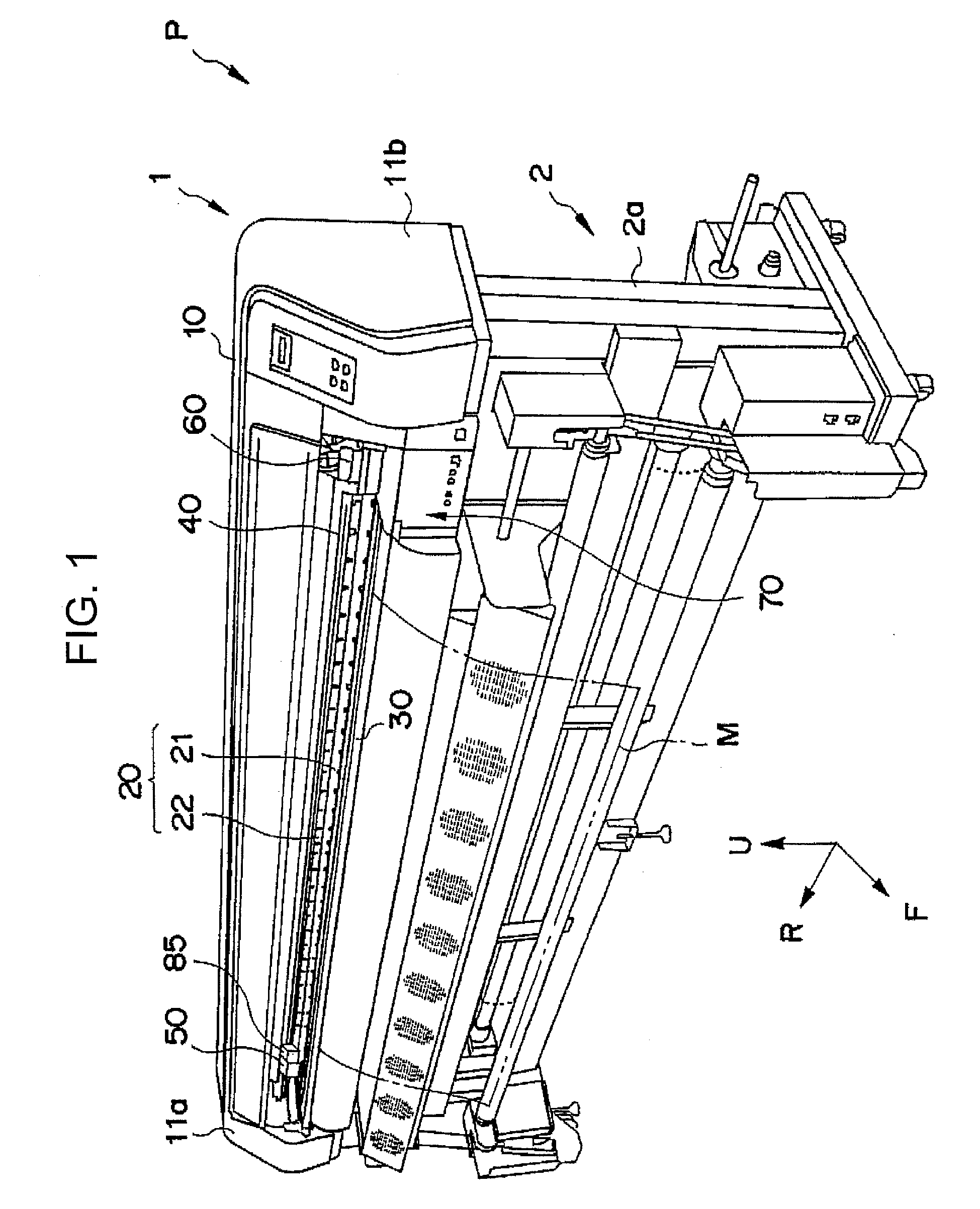
[0026]The embodiments will now be described with reference to the accompanying drawings, wherein like reference numerals designate corresponding or identical elements throughout the various drawings. It should be noted that the directions of arrows F, R, U marked in the drawings are forward, rightward, upward in the following description, respectively.

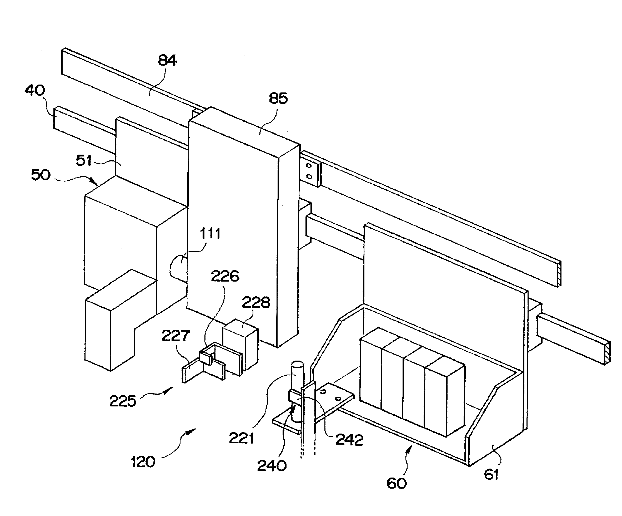
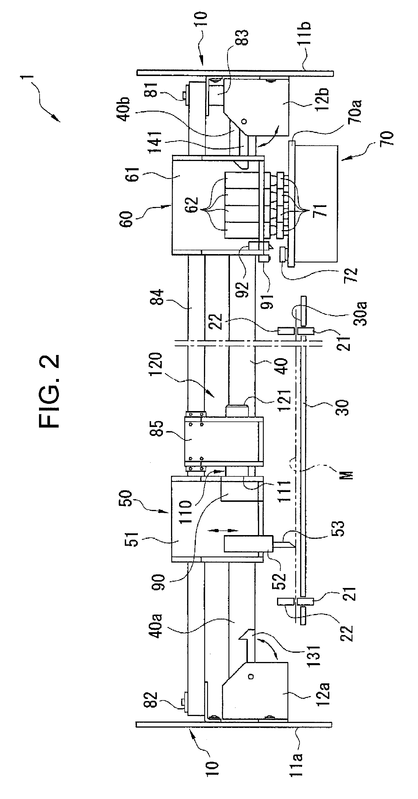
[0027]A printer-plotter of which entire appearance is shown in FIG. 1 includes a main unit 1 for conducting a predetermined action such as printing to a sheet-like medium M such as a roll of paper and a supporting unit 2 having a pair of right and left legs 2a by which the main unit 1 is supported. The main unit 1 includes a body 10 fixed to the upper ends of the legs 2a, a feeding mechanism 20 for feeding the sheet-like medium M in the anteroposterior direction, a platen 30 for supporting the sheet-like medium M, a guide rail 40 extending in the lateral direction above the platen 30, a cutting head 50 and an inkjet head 60 which are s...


PUM


Abstract

A printer-plotter includes first and second heads which are supported by a guide rail and are movable along a longitudinal direction of the guide rail, independently. A driving member is supported by the guide rail and configured to move along the longitudinal direction between the first head and the second head. A first connecting mechanism is configured to connect the first head to the driving member detachably. A second connecting mechanism is configured to connect the second head to the driving member detachably. The first head is connected to the driving member by the first connecting mechanism and the second head is separated from the driving member in order to make the first head operate. The second head is connected to the driving member by the second connecting mechanism and the first head is separated from the driving member in order to make the second head operate.

Description

CROSS-REFERENCE TO RELATED APPLICATIONS[0001]The present application claims priority under 35 U.S.C. § 119 to Japanese Patent Application No. 2007-090534, filed Mar. 30, 2007, entitled “Printer-Plotter Apparatus.” The contents of this application are incorporated herein by reference in their entirety.BACKGROUND OF THE INVENTION[0002]1. Field of the Invention[0003]The present invention relates to a printer-plotter and a method for printing and cutting.[0004]2. Discussion of the Background[0005]Printer is an apparatus for printing on a surface of a sheet-like medium by, for example, ejecting ink droplets from an inkjet head while moving the inkjet head in anteroposterior and lateral directions (horizontally) relative to the sheet-like medium. Plotter is an apparatus for conducting the cutting process relative to a sheet-like medium by moving a cutting head in anteroposterior and lateral directions relative to the sheet-like medium while holding a cutter of the cutting head in contact ...

Claims


Application Information

Patent Timeline
IPC IPC(8): B41J23/00
CPCB26D7/34B26D11/00B26F1/3806B26F1/3813B41J3/543B41J19/005B41J11/0015B41J11/003B41J11/663B41J11/706B41J11/001G06F3/13
Inventor TAKADA, MASANORIIPPONYARI, TADANORIMIYASHITA, EIJIIKEDA, TETSUHARUKOBAYASHI, AKIO
Owner MIMAKI ENG
Why Eureka
Try Eureka