Printer-plotter

a technology of printing head and slitting plate, which is applied in the field of printing head, can solve the problems of contaminated cutting head, increased size and cost of the apparatus, and operation errors of the cutting head

Active Publication Date: 2011-05-24
MIMAKI ENG
View PDF3 Cites 2 Cited by
  • Summary
  • Abstract
  • Description
  • Claims
  • Application Information

AI Technical Summary

Benefits of technology

[0008]According to the plotter with print function having the aforementioned structure, both two heads are connected and are thus moved together during the printing process. For the movement, large belt driving force is required and an electric motor for driving the belt is thus required to have a large capacity, thus leading to increase in size and cost of the apparatus. Further, since the printer head is connected directly to the cutting head during the printing, ink droplets ejected from the printer head for printing may adhere to the cutting head so that the cutting head may be contaminated. Particularly when a solvent ink is used for printing, coatings of electric wires and harnesses for transmitting power and control signals to electric parts in the cutting head may be dissolved due to the adhesion of the solvent ink, leading to operation error of the cutting head. It should be noted that if the coatings of the electric wires and harnesses are made of a material having ink resistance, there is a problem of high cost of production of the apparatus because such a material is expensive.
[0005]Printer is an apparatus for printing on a surface of a sheet-like medium by, for example, ejecting ink droplets from a printer head (inkjet head) while moving the printer head in anteroposterior and lateral directions (horizontally) relative to the sheet-like medium. Plotter is an apparatus for conducting the cutting process relative to a sheet-like medium by moving a cutting head in anteroposterior and lateral directions relative to the sheet-like medium while holding a cutter of the cutting head in contact with the sheet-like medium. For moving each of the heads of these apparatuses in the anteroposterior and lateral directions relative to the sheet-like medium, there is known an arrangement in which the head is supported by a guide rail extending in the lateral direction above the medium such that the head is movable in the lateral direction along the guide rail and the sheet-like medium is fed in the anteroposterior direction. There is also known an arrangement in which the sheet-like medium is fixed and supported on a flat plate and a guide rail which supports the head movably in the lateral direction moves in the anteroposterior direction above the sheet-like medium which is fixed as mentioned above.

Problems solved by technology

For the movement, large belt driving force is required and an electric motor for driving the belt is thus required to have a large capacity, thus leading to increase in size and cost of the apparatus.
Further, since the printer head is connected directly to the cutting head during the printing, ink droplets ejected from the printer head for printing may adhere to the cutting head so that the cutting head may be contaminated.
Particularly when a solvent ink is used for printing, coatings of electric wires and harnesses for transmitting power and control signals to electric parts in the cutting head may be dissolved due to the adhesion of the solvent ink, leading to operation error of the cutting head.
It should be noted that if the coatings of the electric wires and harnesses are made of a material having ink resistance, there is a problem of high cost of production of the apparatus because such a material is expensive.

Method used


Image

  • Printer-plotter
  • Printer-plotter
  • Printer-plotter

Examples


Embodiment Construction

[0018]The embodiments will now be described with reference to the accompanying drawings, wherein like reference numerals designate corresponding or identical elements throughout the various drawings. It should be noted that the directions of arrows F, R, U marked in the drawings are forward, rightward, upward in the following description, respectively.

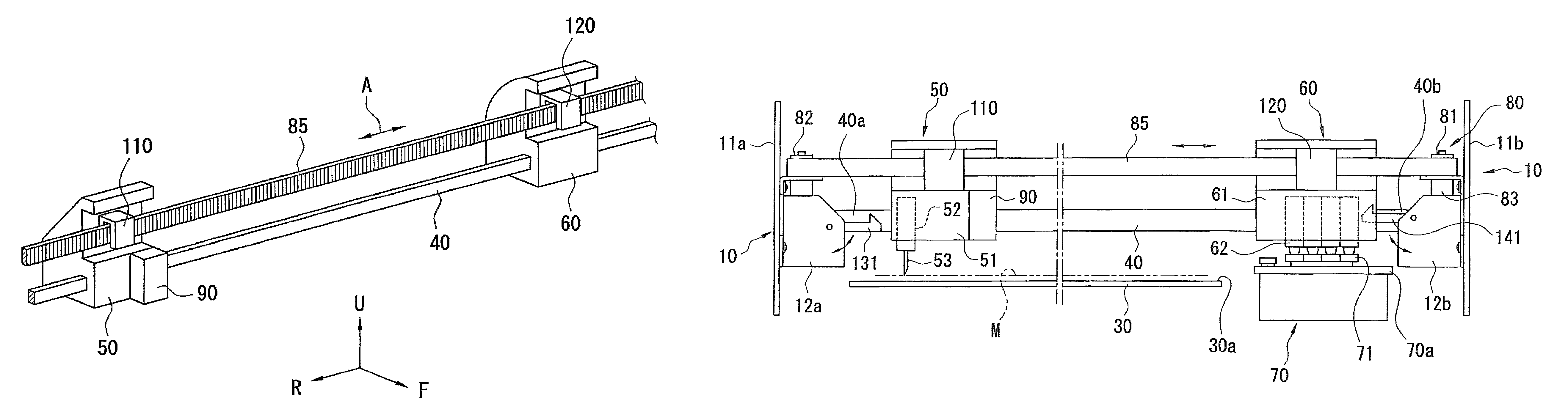
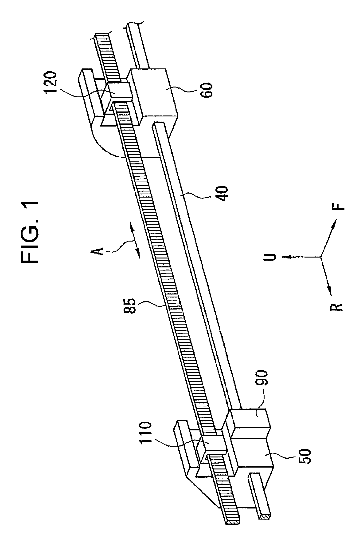
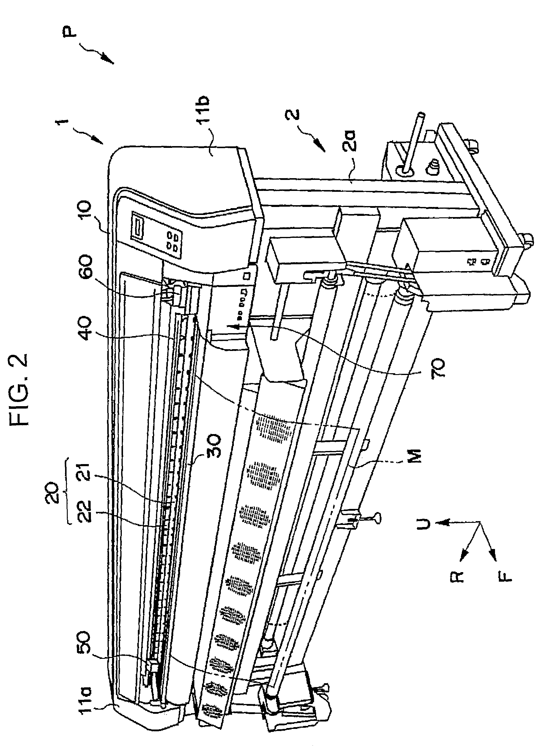
[0019]Shown in FIG. 1 are a guide rail 40, a cutting head 50 and a printer head 60 (sometimes called “inkjet head”) which are attached to the guide rail 40 movably in the lateral direction, and a driving belt 85 which are components of a printer-plotter. As will be described below, the printer-plotter includes a platen on which a sheet-like medium as a subject to be cut by the cutting head 50 or a subject to be printed by the printer head 60 is put, and a feeding mechanism for feeding the sheet-like medium put on the platen in the anteroposterior direction. The guide rail 40 extends in the lateral direction above the platen. The cuttin...


PUM


Abstract

A printer-plotter includes a guide rail, a first head, a second head, a driving device, a first connecting mechanism and a second connecting mechanism. The guide rail extends in a longitudinal direction. The first head is supported by the guide rail and movable along the longitudinal direction. The second head is supported by the guide rail and movable independently of the first head along the longitudinal direction. The driving device includes a driving force transmitting member and a driving mechanism configured to move the driving force transmitting member. The first connecting mechanism is configured to detachably connect the first head to the driving force transmitting member. The second connecting mechanism is configured to detachably connect the second head to the driving force transmitting member.

Description

CROSS-REFERENCE TO RELATED APPLICATIONS[0001]The present application claims priority under 35 U.S.C. §119 to Japanese Patent Application No. 2007-090535, filed Mar. 30, 2007, entitled “Printer-Plotter Apparatus.” The contents of this application are incorporated herein by reference in their entirety.BACKGROUND OF THE INVENTION[0002]1. Field of the Invention[0003]The present invention relates to a printer-plotter.[0004]2. Discussion of the Background[0005]Printer is an apparatus for printing on a surface of a sheet-like medium by, for example, ejecting ink droplets from a printer head (inkjet head) while moving the printer head in anteroposterior and lateral directions (horizontally) relative to the sheet-like medium. Plotter is an apparatus for conducting the cutting process relative to a sheet-like medium by moving a cutting head in anteroposterior and lateral directions relative to the sheet-like medium while holding a cutter of the cutting head in contact with the sheet-like medi...

Claims


Application Information

Patent Timeline
Patent Type & Authority Patents(United States)
IPC IPC(8): H04N1/04
CPCB26F1/3806B26F1/3813B41J19/005B41J3/54B41J11/001B41J11/0015B41J11/706B41J3/28B26D7/34B26D11/00G06F3/13
Inventor TAKADA, MASANORIIPPONYARI, TADANORIMIYASHITA, EIJIIKEDA, TETSUHARUKOBAYASHI, AKIO
Owner MIMAKI ENG
Why Eureka
Try Eureka