Printer-plotter

A head unit and medium technology, applied in printing devices, inking devices, printing, etc., can solve the problems of head unit enlargement, hindering high-speed printing, etc., and achieve the effect of improving printing speed and cutting speed

Inactive Publication Date: 2010-12-22
MIMAKI ENG
View PDF2 Cites 1 Cited by
  • Summary
  • Abstract
  • Description
  • Claims
  • Application Information

AI Technical Summary

Problems solved by technology

However, conventional printing and plotting devices eject normal-color ink and special-color ink from a unitized head unit, so there are problems such as increasing the size of the head unit and hindering high-speed printing and high-speed cutting.

Method used


Image

  • Printer-plotter
  • Printer-plotter
  • Printer-plotter

Examples


Embodiment Construction

[0028] Next, preferred embodiments of the printing and plotting device of the present invention will be described in detail with reference to the accompanying drawings. In addition, in all drawings, the same code|symbol is attached|subjected to the same or corresponding part.

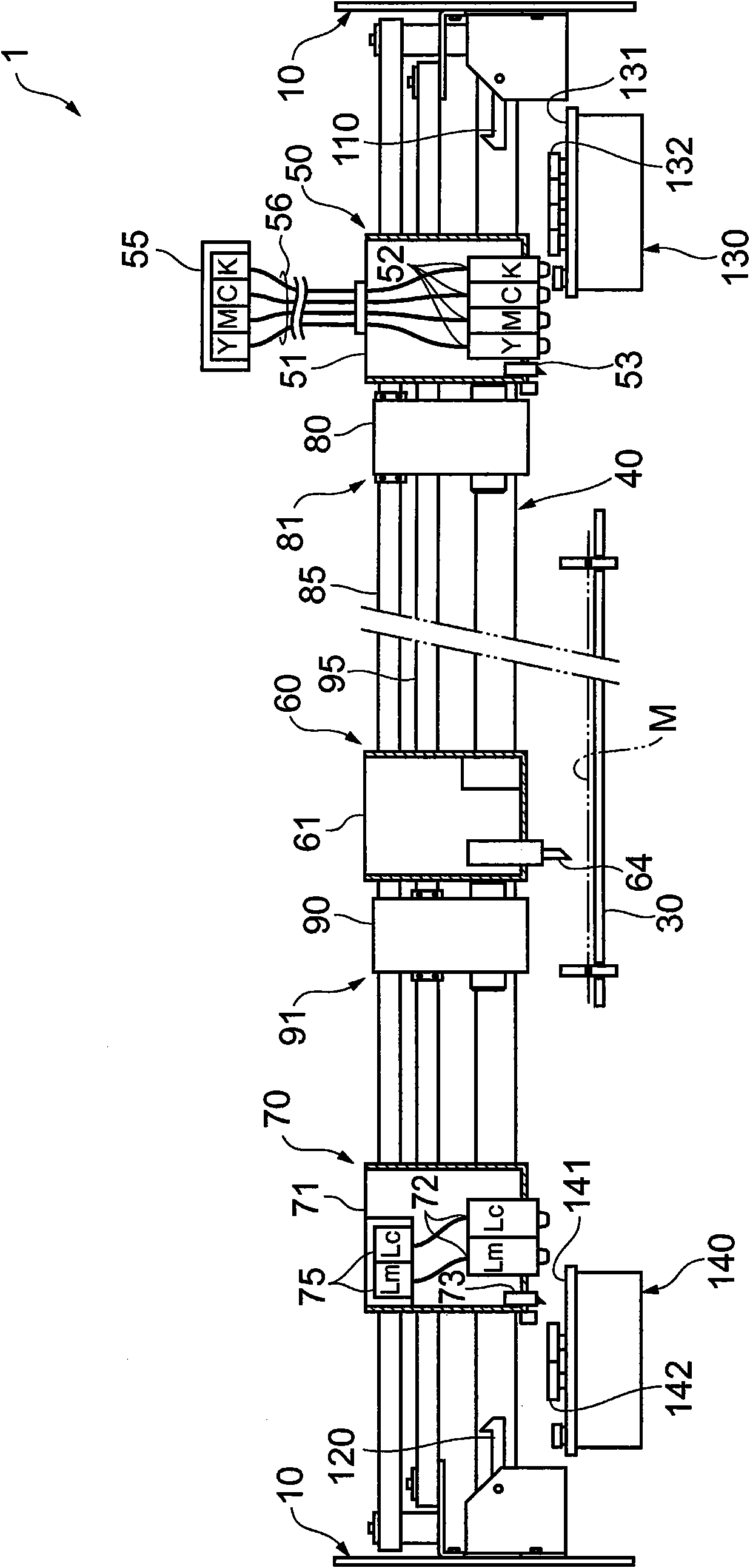
[0029] figure 1 It is a partial enlarged view of the printer and plotter of this embodiment. The printer 1 of the present embodiment prints an image on the medium M placed on the platen 30 and cuts the medium M. Such as figure 1 As shown, on the main body 10 of the printing and plotting device 1 , above the platen 30 supporting the medium M, a guide rail 40 extending along the extending direction of the platen 30 is fixed.

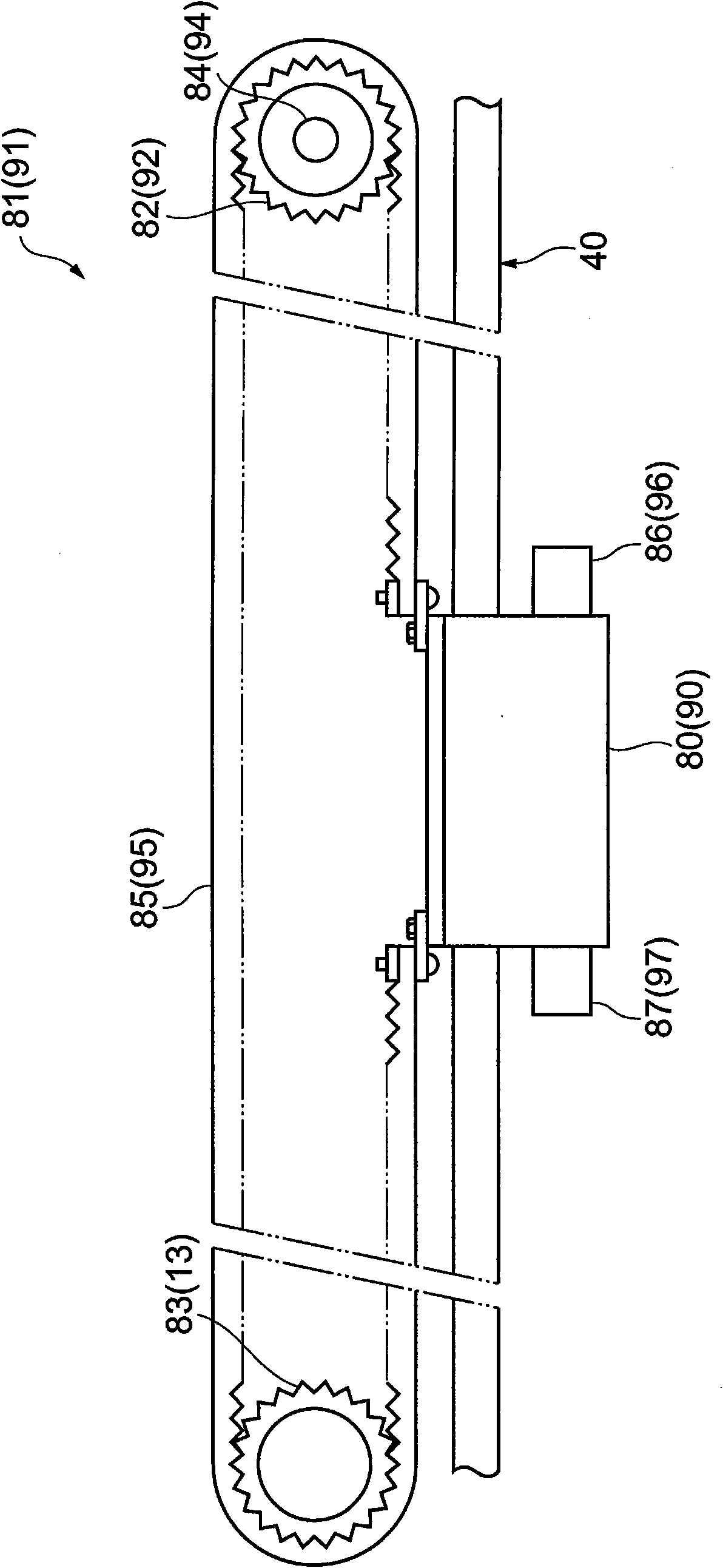
[0030] On the guide rail 40 , a head unit 50 for a normal color, a cutter unit 60 , and a head unit 70 for a special color are slidably supported in this order from the end. In addition, in the following description, the approaching or departing direction of the platen 30 relati...


PUM


Abstract

A printing speed and a cutting speed are improved. A head unit (50) for normal colors which jets a normal-color ink, a cutter unit (60) for cutting, and a head unit (70) for special colors which jets a special-color ink are slidably supported on a guide rail (40) in the named order from the end of the rail. Between the end a head unit (50) and the cutter unit (60), a first driving carriage (80) moving from side to side is disposed; between the cutter unit (60) and the head unit (70), a second driving carriage (90) moving in left and right directions is disposed. Controlling the driving of thefirst driving carriage (80) and the second driving carriage (90) can allow the head unit (50), the cutter unit (60), and the head unit (70) to separately move in left and right direction along the guide rail (40).

Description

technical field [0001] The present invention relates to a printing and plotting device for ejecting ink onto a medium for printing and cutting the medium. Background technique [0002] Conventionally, a printing plotter (cutting plotter) including a head unit that ejects ink onto a medium to perform printing and a cutter unit that cuts the medium is known. [0003] In this printing and plotting device, a head unit and a cutter unit are movably held on guide rails arranged above a platen. The cutter unit is mounted on a belt driven by the driving force of the motor, and can move along the guide rail driven by the belt. On the other hand, the head unit is detachably connected to the cutter unit, and can move along the guide rail as the cutter unit moves (for example, refer to Patent Documents 1 and 2). [0004] Patent Document 1: Japanese Patent Application Laid-Open No. 09-058016 [0005] In recent years, in order to improve the quality of printed images, in addition to th...

Claims


Application Information

Patent Timeline
Patent Type & Authority Applications(China)
IPC IPC(8): B41J11/66B41J2/01
CPCB41J3/543B41J2/2103B41J11/66B41J29/38B41J2202/19
Inventor 池田明大西胜小林昭夫
Owner MIMAKI ENG
Why Eureka
Try Eureka