
Ink tank and method for manufacturing the same

a technology of ink tanks and ink supply, which is applied in the field of ink tanks, can solve the problems of ink scattering, ink flowing out through the ink supply port, and the tendency to consume a greater amount of ink, so as to suppress the scattering and reduce the amount of ink leaked

Inactive Publication Date: 2008-10-02
CANON KK
View PDF4 Cites 36 Cited by
  • Summary
  • Abstract
  • Description
  • Claims
  • Application Information

AI Technical Summary

Benefits of technology

[0016]The present invention is directed to an ink tank which can reduce the amount of ink leaked into an ink supply port and suppress ink scattering when breaking a seal of the ink tank.
[0020]According to the exemplary embodiments of the present invention, ink leakage to the supply port space caused by a temperature change or a pressure change likely to occur during ink tank transportation can be suppressed, and ink scattering when a user opens the cap member can be reduced.

Problems solved by technology

Recently, to carry out high-speed printing of a great deal of data, there is an increasing tendency to consume a greater amount of ink.
However, if such an ink tank is configured to seal an ink supply port with a seal member as in the conventional case, a temperature change or a pressure change during tank transportation or delivery may cause ink to flow out through the ink supply port.
As a result, when the seal member or the cap is removed when the ink tank is used, the ink can be scattered.
However, when the ink moves, flow resistance is small.
However, the step formed in a tip shape of the ink supply port shows a complex configuration in terms of manufacturing, and the sealing with the sealing member at the two places also requires a complex process.
In addition, while the leaked ink can partly be retained at the step portion 1018, its effect is not always satisfactory.
As a result, the amount of ink supplied from the ink tank to the head runs short, which causes a printing failure or ink use efficiency in the ink tank tends to decline.
A similar problem occurs in the ink tank which holds the ink by the ink containing member including a sponge as discussed in U.S. Pat. No. 5,701,995 or Japanese Patent Application No. 08-112915.
However, when the ink containing member (porous member) occupying the major part in the tank includes a capillary member such as a sponge, it is difficult to completely remove air from the ink containing member.
The air in the ink containing member expands, so that the ink in the ink containing member may be pushed to the ink supply port side, causing ink leakage from the vicinity of the supply port.
The larger the ink containing member, the greater an amount of residual air in the ink containing member, which increases ink leakage to the ink supply port.
However, in the thus configured tank, since the ink is held by the ink containing member disposed in the ink containing chamber, therefore the amount of ink which can be held is small for a volume of the tank, which causes enlarging of the ink tank.

Method used


Image

  • Ink tank and method for manufacturing the same
  • Ink tank and method for manufacturing the same
  • Ink tank and method for manufacturing the same

Examples


first exemplary embodiment

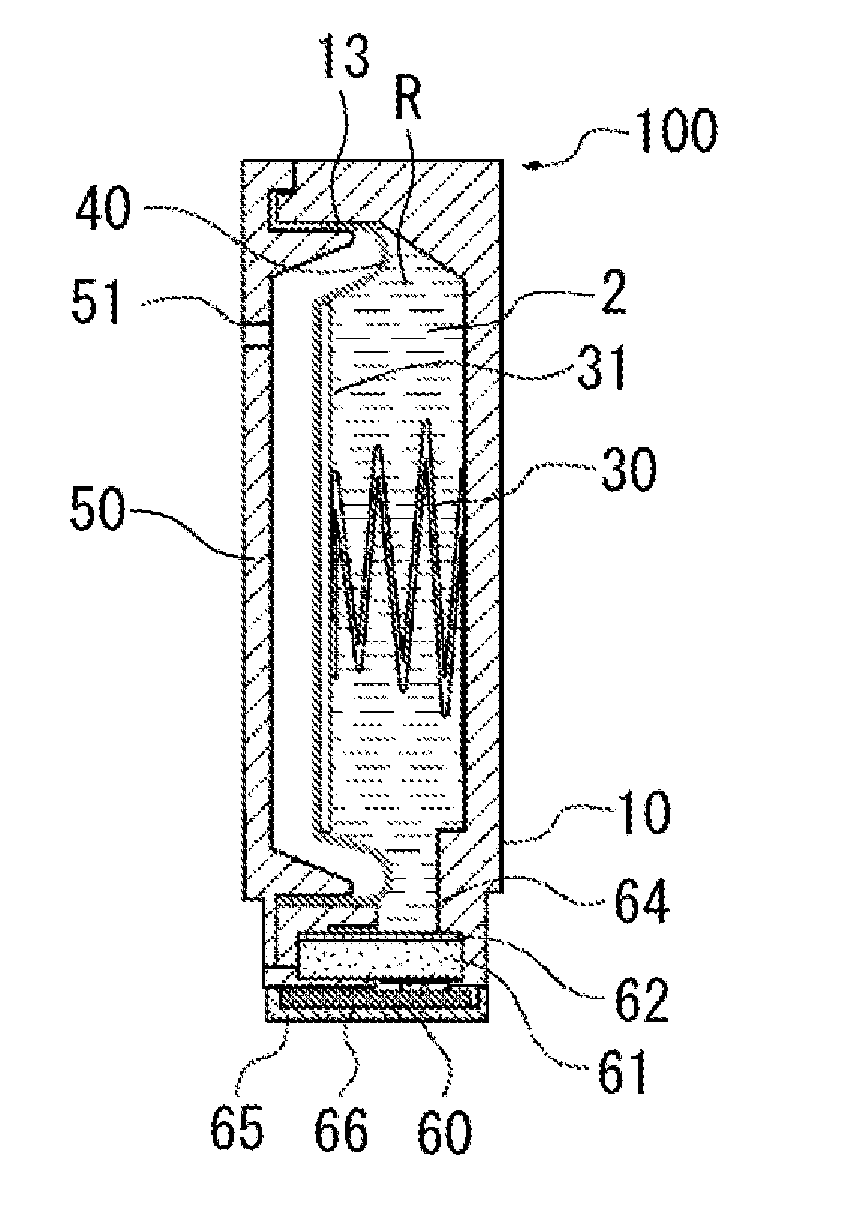
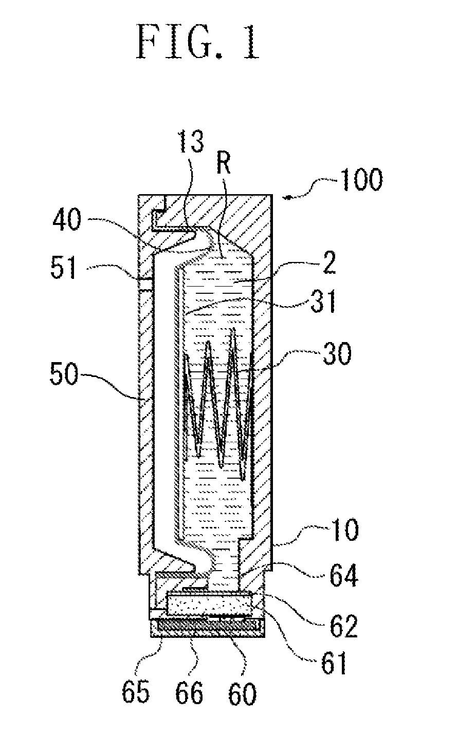
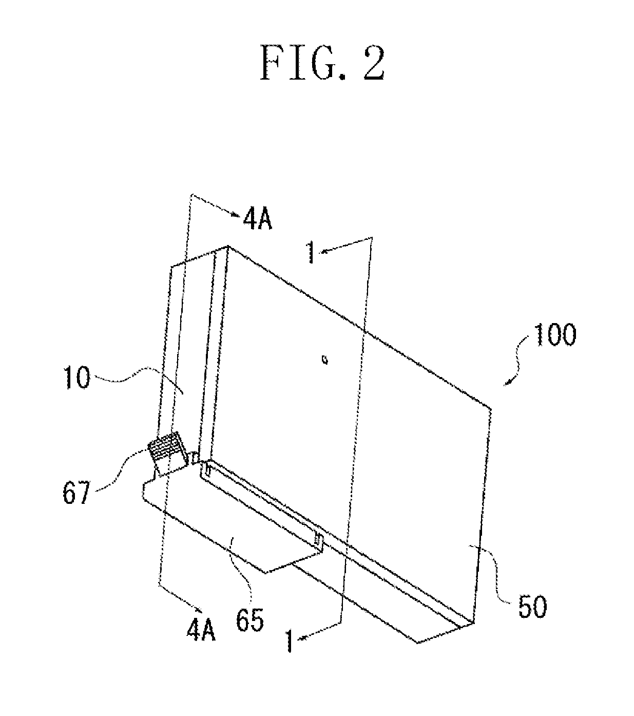
[0040]FIG. 1 is a sectional diagram of an ink tank 100 according to a first exemplary embodiment of the present invention. FIG. 2 is a perspective diagram of the ink tank 100. FIG. 1 corresponds to a sectional diagram cut on the line I-I of FIG. 2. FIG. 3 is an exploded perspective diagram of the ink tank 100. Each of FIGS. 4A to 4C corresponds to a sectional diagram cut on the line 4A-4A of FIG. 2.

(Configuration of Ink Tank)

[0041]The ink tank 100 is a container for containing ink 2 in an ink containing chamber R which includes a tank case 10 and a flexible member 40. An ink guide port 64 disposed in the ink containing chamber R communicates with an ink supply port 60. The ink supply port 60 is connected to an ink supply path of an ink jet recording head. When the ink tank 100 is transported / delivered, in order to prevent ink leakage from the ink supply port 60, the ink supply port 60 is sealed with a cap member 65 having a sealing member 66 attached thereto. The sealing member 66 i...

second exemplary embodiment

[0063]FIG. 6 is a sectional diagram of an ink tank according to a second exemplary embodiment of the present invention.

[0064]According to the second exemplary embodiment, a cap member is a film member 71. If it is the cap member that seals the supply port space 70, the elastic sealing member is coupled to the highly rigid cap member. According to the second exemplary embodiment, however, the supply port space 70 is sealed only with the film member 71 having an adhesive layer. According to the second exemplary embodiment, as in the case of the first exemplary embodiment, it may be configured such that the conditional equation (1) or (2) is satisfied. According to the second exemplary embodiment, manufacturing costs can be reduced since the simply configured film member 71 can be used.

[0065]As in the case of the first exemplary embodiment, the present exemplary embodiment provides an ink dripping suppression effect when air expands in the supply port 60 when a temperature increases or...


PUM

PropertyMeasurementUnit
Pressureaaaaaaaaaa
Volumeaaaaaaaaaa

Abstract

An ink tank includes an ink containing chamber configured to directly contain ink, a supply port configured to supply the ink from the ink containing chamber to a recording head, a capillary member disposed in the supply port to hold the ink, and a sealing member configured to cover the supply port. An air volume (V) of a space constituted by the capillary member and the sealing member, an ink volume (Vi) held by the capillary member, and a maximum volume (Vexp) when air expands in the space accompanying environmental fluctuation of the ink tank, satisfy Vi≧Vexp−V.

Description

BACKGROUND OF THE INVENTION[0001]1. Field of the Invention[0002]The present invention relates to an ink tank installed and used in an ink jet recording apparatus, and its manufacturing method.[0003]2. Description of the Related Art[0004]Conventionally, an ink jet recording head for discharging ink to carry out recording, and an ink tank for holding and supplying ink to the recording head can be roughly classified into the following two types: a head-integrated ink cartridge in which the recording head and the ink tank are integrated, and a replaceable ink cartridge in which the recording head and the ink tank are detachable from each other. In the case of the replaceable ink cartridge, when there is no more ink in the ink tank, the cartridge can still be used by replacing only the ink tank. Thus, the replaceable ink cartridge is generally advantageous in running costs.[0005]For the replaceable ink cartridge of this type, some configurations have been devised to prevent ink leakage a...

Claims


Application Information

Patent Timeline
IPC IPC(8): B41J2/175
CPCB41J2/17513Y10T29/49401B41J2/17556
Inventor INOUE, RYOJIKOTAKI, YASUOOHASHI, TETSUYATAKADA, HITOSHIOGURA, HIDEKIKUBO, KOUICHINANJO, TATSUO
Owner CANON KK
Features
  • Generate Ideas
  • Intellectual Property
  • Life Sciences
  • Materials
  • Tech Scout
  • Unparalleled Data Quality
  • Higher Quality Content
  • 60% Fewer Hallucinations
Learn More