Inkjet printing apparatus and printhead driving method

a printing apparatus and printing head technology, applied in printing, other printing apparatus, etc., can solve the problems of reducing affecting the printing performance of printing, and clogging of discharge failures and other problems, so as to improve printing performance, and reduce the amount of ink mist

Inactive Publication Date: 2009-01-22
CANON KK
View PDF3 Cites 0 Cited by
  • Summary
  • Abstract
  • Description
  • Claims
  • Application Information

AI Technical Summary

Benefits of technology

[0021]In accordance with the present invention as described above, the driving time interval between neighboring nozzles is changed between printing and preliminary discharge by selecting a discharge method excellent in printing performance in printing, and a discharge method which reduces the amount of ink mist in preliminary discharge.
[0022]The invention is particularly advantageous since the amount of ink mist can be greatly reduced by this relatively simple method while maintaining high image quality.

Problems solved by technology

Since inkjet printing uses ink whose main component is water, the viscosity of ink increases upon evaporation of water or the like, and a discharge failure and clogging readily occur.
Satellite droplets cause various problems.
For example, an ink droplet of a smaller particle diameter is more susceptible to the influence of air resistance.
Thus, under the influence of an air flow generated when a main droplet passes through air, a subsequent satellite droplet might attach to an unintended portion on a print medium, degrading the image quality.
Further, satellite droplets of extraordinarily small particle diameter do not attach to a print medium, but float as ink mist and contaminates the interior of the apparatus.
However, the state in which crosstalk occurs is an unstable state, and crosstalk is likely to influence printing.
That is, if the driving time interval between adjacent nozzles is set large in order to prevent degradation of the image quality, this causes a problem that floating ink mist increases in preliminary discharge and contaminates the interior of the apparatus.
On the contrary, if the driving time interval between adjacent nozzles is adjusted to an interval at which crosstalk easily occurs in order to reduce floating ink mist, this causes a problem that degradation of the image quality cannot be prevented.

Method used


Image

  • Inkjet printing apparatus and printhead driving method
  • Inkjet printing apparatus and printhead driving method
  • Inkjet printing apparatus and printhead driving method

Examples


first embodiment

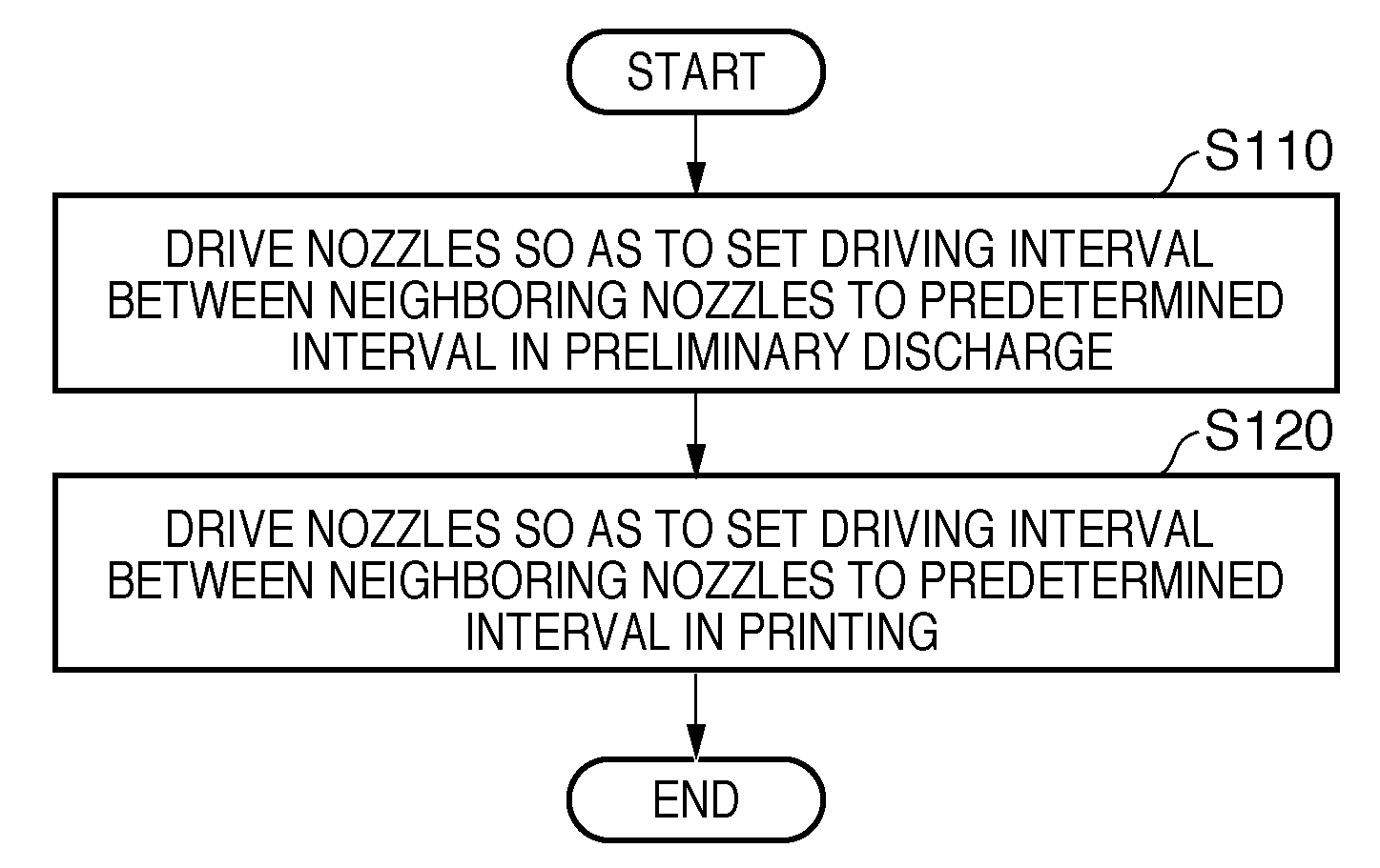
[0058]As a method of driving a printhead 3 in the above-described inkjet printing apparatus, the apparatus employs a block division driving method of dividing a plurality of orifices into a plurality of blocks and simultaneously driving orifices of each block. The time intervals at which respective blocks are driven are equal, are called block intervals, and represented by tb in this specification.

[0059]The first embodiment uses a printhead in which nozzles arrayed in line are divided into 16 blocks and time-divisionally driven.

[0060]FIG. 1 is a driving timing chart for 16 adjacent nozzles of the printhead in printing. The left side of FIG. 1 shows the orifices of 16 adjacent nozzles, and driving signals corresponding to the respective orifices are shown in a predetermined sequence from the left to right in FIG. 1. The respective orifices start the discharge operation in accordance with the driving signals.

[0061]In printing, it is desirably designed to perform the discharge operatio...

second embodiment

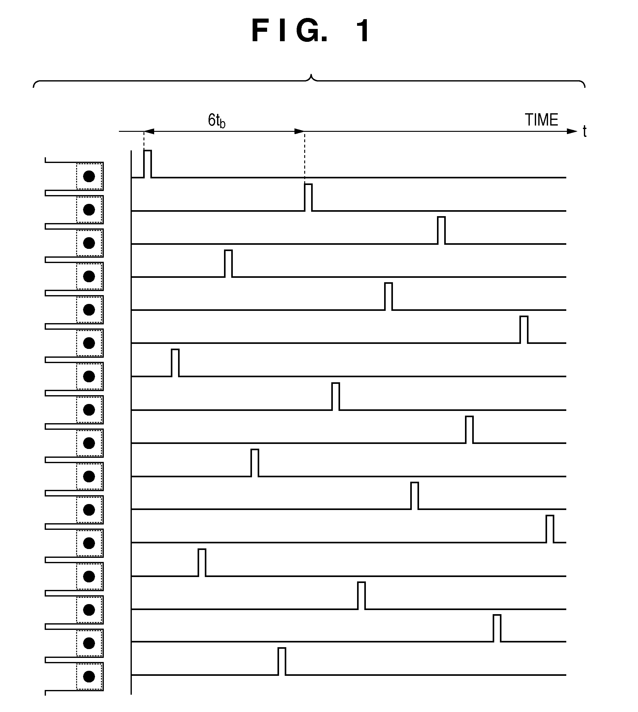
[0072]Similar to the first embodiment, the second embodiment uses a printhead in which nozzles arrayed in line are divided into 16 blocks and time-divisionally driven.

[0073]In the second embodiment, the drive sequence of nozzles in printing is the same as that described with reference to FIG. 1. This drive sequence maximizes the time interval at which adjacent nozzles are driven, and reduces the influence of crosstalk.

[0074]FIG. 6 shows the drive sequence of nozzles in preliminary discharge according to the second embodiment. As shown in the timing chart of FIG. 6, the time interval at which adjacent nozzles are driven is double the block interval, that is, 2 tb at each orifice. At this time, by setting the block interval to 1.0 μs (inclusive) to 2.5 μs (inclusive), the time interval at which adjacent nozzles are driven becomes 2.0 μs (inclusive) to 5.0 μs (inclusive). With these settings, discharge starts when the meniscus of an orifice is convex, and thus discharge almost free fro...


PUM


Abstract

An object of this invention is to decrease the amount of ink mist while keeping the image quality high in inkjet printing. To achieve this object, printing is performed by time-divisionally driving, for each block, a plurality of nozzles for discharging ink. In preliminary discharge, the nozzles are so driven as to set the driving time interval between neighboring nozzles to the first time interval. In printing, the nozzles are so driven as to set the driving time interval between neighboring nozzles to the second time interval longer than the first time interval.

Description

BACKGROUND OF THE INVENTION[0001]1. Field of the Invention[0002]The present invention relates to an inkjet printing apparatus capable of discharging liquid by applying energy to the liquid, and a method of driving a printhead used in the inkjet printing apparatus.[0003]2. Description of the Related Art[0004]Inkjet printing apparatuses are mainly used to print photographs and postcards, and have advantages of high-speed printing, high quality, low noise, and printing on a variety of media. Along with recent popularization of digital cameras and personal computers, the market of inkjet printing apparatuses is growing rapidly. The range of use of the inkjet technique is becoming wider such that the inkjet technique of discharging a predetermined amount of droplet and attaching it to a print medium is exploited in the industrial field. Along with this, the printhead used in the inkjet printing apparatus is improving its performance more and more, and the technical innovation is accelera...

Claims


Application Information

Patent Timeline
Patent Type & Authority Applications(United States)
IPC IPC(8): B41J29/38
CPCB41J2/04558B41J2/04573B41J2/0458B41J2/04588
Inventor IMAHASHI, YUSUKEINOUE, TAKASHI
Owner CANON KK
Why Eureka
Try Eureka