Method of driving a printhead using a constant current and operating MOS transistor in saturation region

a technology of constant current and mos transistor, which is applied in the field of driving a printhead using a constant current and operating mos transistor in the saturation region, can solve the problems of low running cost of the inkjet printing apparatus, inability to connect the heating resistance elements by a traditional electrical connection method, and the pitch between the electrode pads of the heating resistance elements is reduced, so as to achieve excellent printing quality and small power loss

Inactive Publication Date: 2007-05-15
CANON KK
View PDF55 Cites 38 Cited by
  • Summary
  • Abstract
  • Description
  • Claims
  • Application Information

AI Technical Summary

Benefits of technology

[0066]For example, a printhead substrate according to the present invention is capable of suppressing an increase in wiring width and an increase in the size of a substrate formed by a film forming process while increasing the number of simultaneously driven printing elements in order to improve the printing performance.
[0086]In this manner, a method of driving a printhead excellent in printing characteristic regardless of variations in the resistance value of the printing element is implemented without greatly changing a conventional configuration.
[0088]The invention is particularly advantageous since energy applied to the printing element is made constant by driving the printing element of the printhead at a constant current, variations in energy applied to the printing element upon a change in the number of simultaneously driven printing elements can be suppressed, and high-quality printing can be achieved.
[0091]As a result, high-quality printing excellent in printing characteristic with a small power loss can be realized.

Problems solved by technology

In addition, the running cost of the inkjet printing apparatus is low, and the inkjet printing apparatus hardly generates noise because of non-impact printing and can print a color image by using multicolor ink.
When heating resistance elements are arrayed at a high density, the pitch between the electrode pads of the heating resistance elements decreases, and the heating resistance elements cannot be connected by a traditional electrical connection method (wire bonding or the like).
However, the driving time assigned to each heating resistance element becomes shorter, and must be further shortened for higher-frequency driving.
However, even this method still requires a certain driving time, and the driving time has already reached its limit in the conventional method.
However, the minimum wiring width is limited by the manufacture, and a thicker wiring line is required as the number of wiring lines increases.
In practice, when the number of simultaneously driven heating resistance elements is doubled, the wiring width increases three or four times, resulting in an abrupt increase in substrate size.
Along with this, the number of simultaneously driven heating resistance elements inevitably increases.
This adversely affects the stability of ink discharge and the durability of the printhead.
This generates a fault such as degradation of the printing quality owing to energy variations.
However, when a constant current is commonly supplied to the heaters of a plurality of substrates in order to eliminate variations in energy caused by the difference in the number of simultaneously driven printing elements, like the prior art, the power loss on the inkjet printhead substrate by variations in the resistance of the printing element greatly changes.
Particularly, when the resistance value of the printing element is 80 Ω, about 58% of energy applied to the printing element is lost.
Hence, the fact that variations by about 20% to 30% in the resistance value of the printing element in manufacturing the printhead cannot be avoided means that it is very difficult to provide an inkjet printhead having uniform ink discharge performance.
As described above, when the method of driving the printing element at a constant current in order to eliminate the difference caused by a change in the number of simultaneously driven printing elements is introduced, energy is wastefully consumed owing to variations in the resistance value of the printing element in the printhead manufacturing process.

Method used


Image

  • Method of driving a printhead using a constant current and operating MOS transistor in saturation region
  • Method of driving a printhead using a constant current and operating MOS transistor in saturation region
  • Method of driving a printhead using a constant current and operating MOS transistor in saturation region

Examples


first embodiment

[0179]FIG. 9 is a graph showing the relationship between the ink discharge speed and the voltage applied to both ends of the heating resistance element.

[0180]FIG. 9 represents the ink discharge state in terms of a discharge speed v as a function of a voltage V (energy E) between both ends of a heating resistance element 1103. Since the ink discharge state changes in accordance with the voltage (energy), electrode wiring lines are conventionally individually laid out up to electrode pads for a set of simultaneously driven heating resistance elements on the substrate so that the potential difference between both ends of the heating resistance element falls within a stable discharge range in accordance with the number of simultaneously driven heating resistance elements.

[0181]The range within which ink can be actually stably discharged is the range of a stable region shown in FIG. 9, and this range generally is within ±5% in view of the potential difference between both ends of the hea...

second embodiment

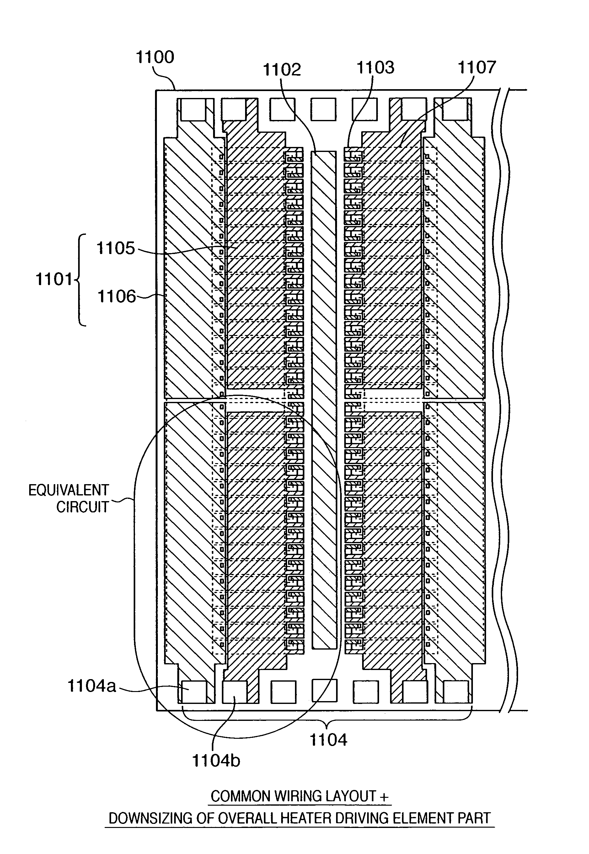
[0217]FIG. 17 is a block diagram showing the configurations of an inkjet printhead substrate (to be referred to as a substrate hereinafter) 1100 according to the second embodiment of the present invention, a printhead 3 integrating the substrate, and a part, of a printing apparatus using the printhead, which influences energy applied to a printing element.

[0218]The apparatus main body comprises a power supply which supplies power to the printhead and printing element substrate, and the power supply supplies a predetermined voltage and current to the element substrate.

[0219]A description of a part which is identical to that of a conventional substrate described with reference to FIGS. 27 to 32 will be omitted, and only a characteristic part of the second embodiment to which the present invention is applied will be described.

[0220]In FIG. 17, reference numeral 2101 denotes each printing element (heating resistance element); and 2102, each printing element switching element (driver) fo...


PUM


Abstract

This invention relates to a printhead substrate capable of suppressing an increase in wiring width and an increase in the size of a substrate formed by a film forming process while increasing the number of simultaneously driven printing elements in order to improve the printing performance, a printhead using the substrate, and a printing apparatus using the printhead. The wiring lines of the substrate are formed into a common wiring line, and energy applied to a heating resistance element is prevented from deviating from a stable ink discharge range owing to the difference in the number of simultaneously driven heating resistance elements. For this purpose, a driving element is greatly downsized in comparison with a conventional one, and the operation region of a MOS transistor is shifted from the non-saturation region to the saturation region.

Description

FIELD OF THE INVENTION[0001]This invention relates to a printhead substrate, a printhead using the substrate, a head cartridge including the printhead, a method of driving the printhead, and a printing apparatus using the printhead and, more particularly, to a printhead substrate for a printhead complying with an inkjet method of printing an image or the like by discharging ink onto a printing medium, a printhead using the substrate, a head cartridge including the printhead, a method of driving the printhead, and a printing apparatus using the printhead.BACKGROUND OF THE INVENTION[0002]A printing apparatus having the function of a printer, copying machine, facsimile apparatus, or the like, or a printing apparatus used as an output device for a multifunction apparatus or workstation including a computer, word processor, or the like prints an image on a printing medium such as a printing sheet or thin plastic plate (used for an OHP sheet or the like) on the basis of image information....

Claims


Application Information

Patent Timeline
Patent Type & Authority Patents(United States)
IPC IPC(8): B41J2/05B41J2/14B41J2/175
CPCB41J2/04506B41J2/04541B41J2/04543B41J2/04548B41J2/14072B41J2/04565B41J2/0458B41J2/04591B41J2/04553B41J2/0455B41J2/1404
Inventor IMANAKA, YOSHIYUKIOZAKI, TERUOHATSUI, TAKUYAYAMAGUCHI, TAKAAKISAITO, ICHIROMOCHIZUKI, MUGASAKAI, TOSHIYASU
Owner CANON KK
Why Eureka
Try Eureka