Conductive Paste and Wiring Board Using It

a technology of conductive paste and wiring board, which is applied in the direction of conductive layers on insulating supports, insulating bodies, conductors, etc., can solve the problems of design to difficult to apply conductive paste thickly, and conductive paste cannot be easily applied thickly, so as to suppress the wiring resistance to a low level, enlarge the wiring width, and suppress the effect of low level

Inactive Publication Date: 2009-04-30
SUMITOMO ELECTRIC IND LTD
View PDF9 Cites 15 Cited by
  • Summary
  • Abstract
  • Description
  • Claims
  • Application Information

AI Technical Summary

Benefits of technology

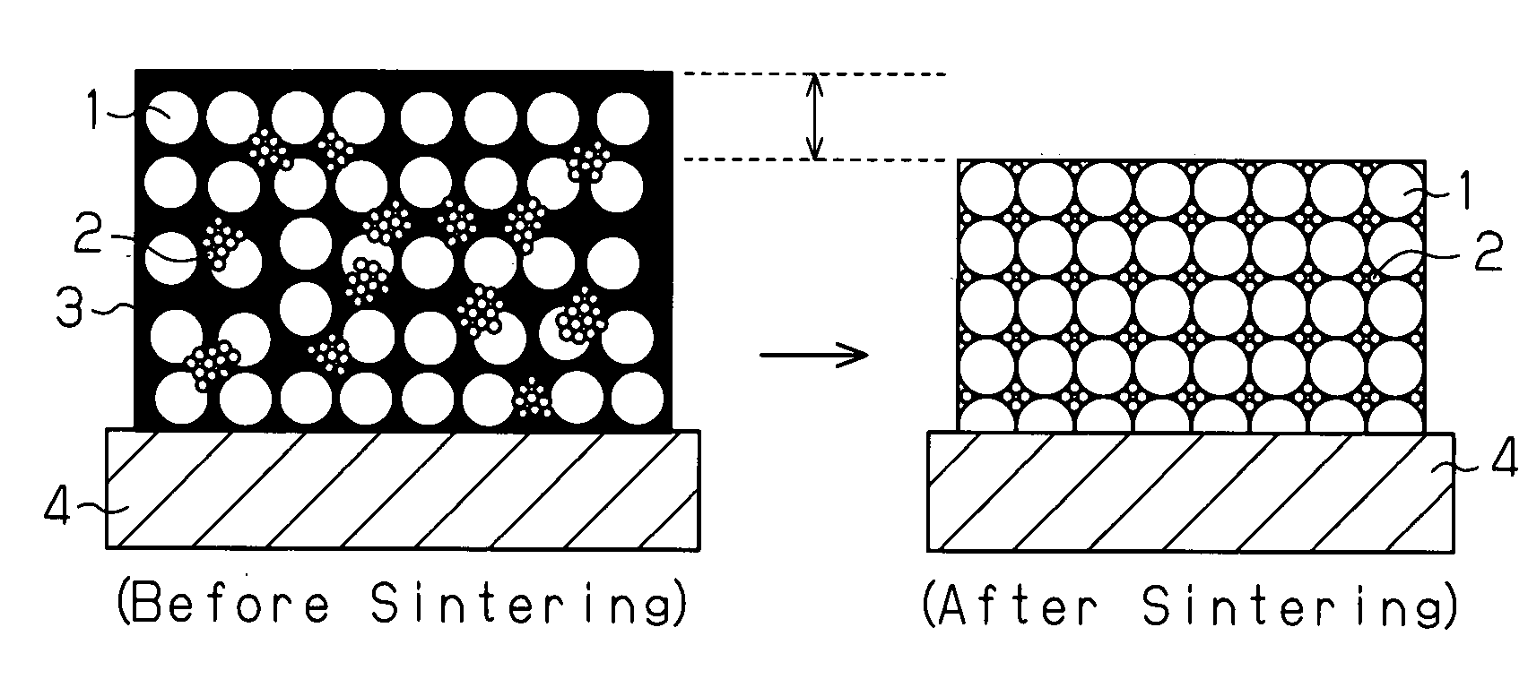
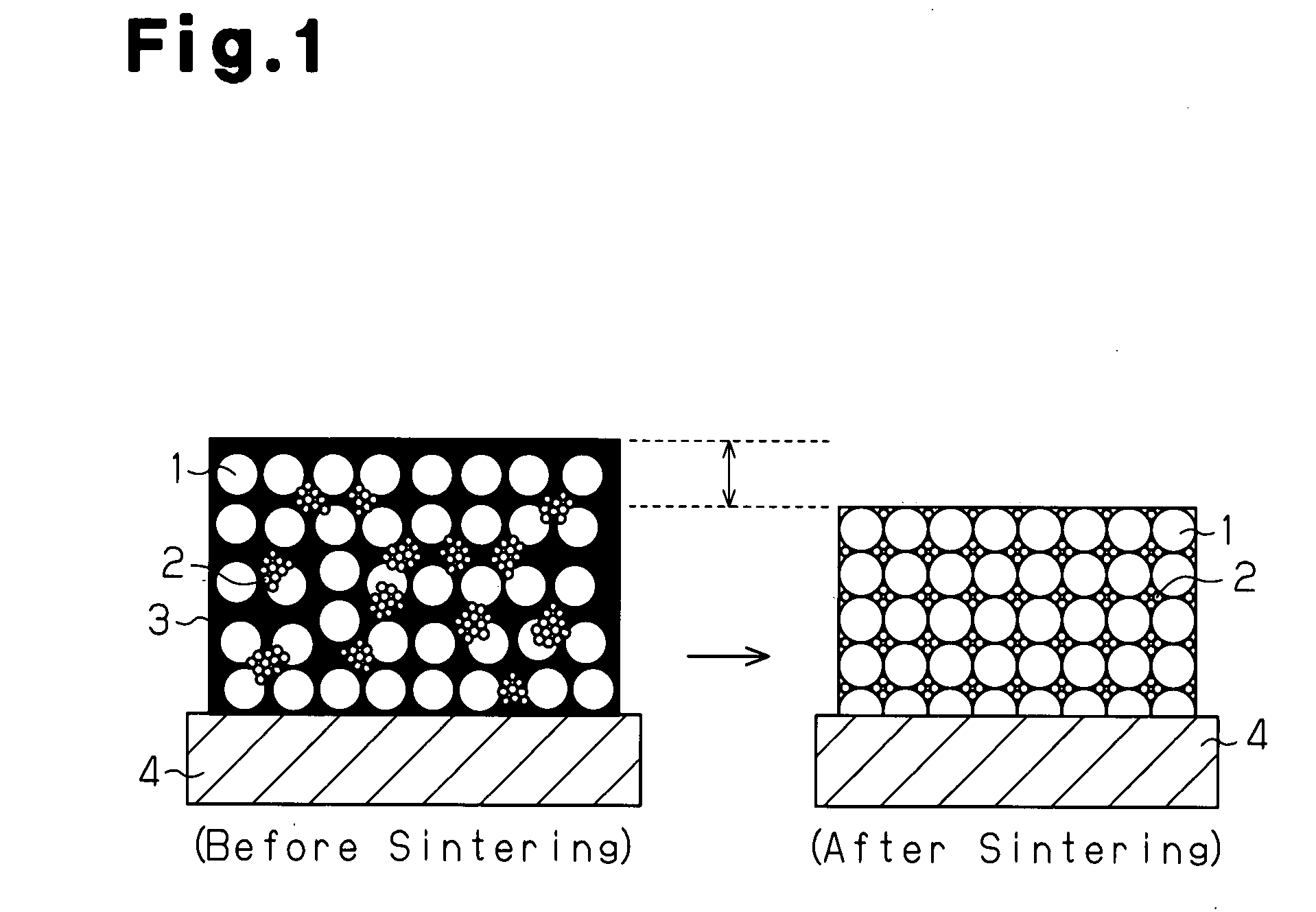
[0006]Generally, sintering type paste for use in wiring is demanded to suppress wiring resistance to a low level. Although enlarging wiring width is effective to suppress the wiring resistance to a low level, it is often difficult in design to enlarge the wiring width and rather, there is a strong demand for narrowing the wiring width. Therefore, to suppress the wiring resistance to a low level, it is necessary to apply conductive paste thickly as well as to lower the volume resistivity of the conductive paste. The conductive paste needs to be sintered sufficiently to obtain high conductive properties and generally, contraction of the conductive paste at the time of drying and sintering is large, so that the thickness after sintering contracts to about 20% of the thickness at the time of application. Thus, to suppress contraction at the time of drying and sintering, the content of metal powder and glass frit with respect to the entire conductive paste needs to be increased.

Problems solved by technology

Although enlarging wiring width is effective to suppress the wiring resistance to a low level, it is often difficult in design to enlarge the wiring width and rather, there is a strong demand for narrowing the wiring width.
As a result, it is difficult to apply conductive paste thickly.
Consequently, the conductive paste cannot be easily applied thickly.

Method used


Image

  • Conductive Paste and Wiring Board Using It
  • Conductive Paste and Wiring Board Using It

Examples


examples

[0047]Hereinafter, the present invention will be described with reference to Examples and Comparative Examples. The present invention is not restricted to these examples, but these examples may be modified or changed based on the spirit of the present invention while such modifications and changes are not excluded from the scope of the present invention.

examples 1-5

[0048]As an organic vehicle, ethyl cellulose (molecular weight of 15000) was dissolved in diethylene glycol monoethyl ether acetate by heating so as to prepare a solution having resin content density of 6, 8 or 10 wt %. Next, silver powder was added to the solution as the metal powder and mixed homogeneously with a rotating agitation defoaming apparatus and further, a glass frit was added and the mixing was continued. After it was determined by visual check that these components were uniform, the solution was passed through a 3-roll mill so as to prepare conductive pastes shown in Examples 1-5 of Table 1 below. No abnormality on appearance in normal condition was observed in the conductive pastes of Examples 1-5. Table 1 shows the kinds and blending quantity of the respective components in Example 1-5.

[0049]In Examples 1-5, the total amount of the contents of silver powder and glass frit with respect to the entire conductive paste was 91 wt %. As the result of measurement with an au...


PUM

PropertyMeasurementUnit
viscosityaaaaaaaaaa
viscosityaaaaaaaaaa
particle average particle diameteraaaaaaaaaa

Abstract

A conductive paste is mainly composed of a metal powder, a glass frit, and an organic vehicle. The total content amount of the metal powder and glass frit with respect to the entire conductive paste is 85 wt % or more. The viscosity at a rotational speed of 1 rpm measured at 25° C. with an E type rotating viscometer is 100 Pa·s or more and 400 Pa·s or less.

Description

FIELD OF THE INVENTION[0001]The present invention relates to conductive paste for use in forming a wiring circuit on a substrate and a wiring board obtained using the same conductive paste.BACKGROUND OF THE INVENTION[0002]The conductive paste containing mainly metal powder as solid content has been widely used in electronic device components since it shows excellent conductive properties and for example, is used as material for an electrically-conductive path when forming an electric circuit on a wiring board. As this conductive paste, a conductive paste produced in a paste state by dispersing, for example metal powder and glass frit, in an organic vehicle is available. Then, the conductive paste is applied to a ceramic, glass substrate or the like by screen printing or the like so as to form a wiring pattern. Next, when the conductive paste is sintered at high temperatures, the organic vehicle is transpired and the metal powder is sintered so as to form a continuous film. Such cond...

Claims


Application Information

Patent Timeline
Patent Type & Authority Applications(United States)
IPC IPC(8): H05K1/09H01B1/02
CPCH05K1/092H01B1/16H01B1/22H01B5/14H01B5/16H01B17/62H01B17/64
Inventor YAMAKAWA, MASAHIROSHIMODA, KOHEI
Owner SUMITOMO ELECTRIC IND LTD
Why Eureka
Try Eureka