Cam follower apparatus

a follower and cam technology, applied in mechanical equipment, machines/engines, roller bearings, etc., can solve the problems of difficult to make the reduction of the weight of the tappet roller compatible with securing durability, and achieve the effect of suppressing the bending stress generated on the tapped roller when the engine is running and preventing damage to the tappet roller

Inactive Publication Date: 2009-02-26
NSK LTD
View PDF2 Cites 11 Cited by
  • Summary
  • Abstract
  • Description
  • Claims
  • Application Information

AI Technical Summary

Benefits of technology

[0035]In the case of the cam follower apparatus of the invention which is configured as has been described heretofore, there occurs no case where the rolling surfaces of the needles which are adjacent in the circumferential direction rub against each other. Although the rolling surfaces of the respective needles and the circumferential sides of the respective separating elements rub against each other, the rubbing speed is slower than (is suppressed to ½) that resulting where the rolling surfaces of the needles which are adjacent in the circumferential direction rub against each other. Because of this, the dynamic torque of the radial needle bearing is suppressed to a low level, whereby the rotational resistance of the tappet roller is suppressed to a low level.
[0036]Furthermore, the thickness of the respective separating element is smaller than the diameter of the respective needle, and moreover, the radial position of the respective separating element is offset relative the radial position of the respective needle (the pitch circle diameter of the respective needles and the pitch circle diameter of the respective separating elements are made to differ). Because of this, the interval between the rolling surfaces of the needles which are adjacent in the circumferential direction can be reduced to become narrower than the circumferential width of the respective separating element so as to secure the number of needles which are disposed between the outer circumferential surface of the support shaft and the inner circumferential surface of the tappet roller. As a result, a bending stress generated on the tapped roller when the engine is running can be suppressed to a small level without increasing the thickness of the tappet roller, so as to realize the prevention of damage to the tappet roller.

Problems solved by technology

Because of this, when the interval between the needles 8, 8 which are adjacent to each other in the circumferential direction is wide, a large bending stress becomes easy to be applied repeatedly to the tappet roller, and it becomes difficult to make reducing the weight of the tappet roller compatible with securing the durability.

Method used


Image

  • Cam follower apparatus
  • Cam follower apparatus
  • Cam follower apparatus

Examples


embodiment 1

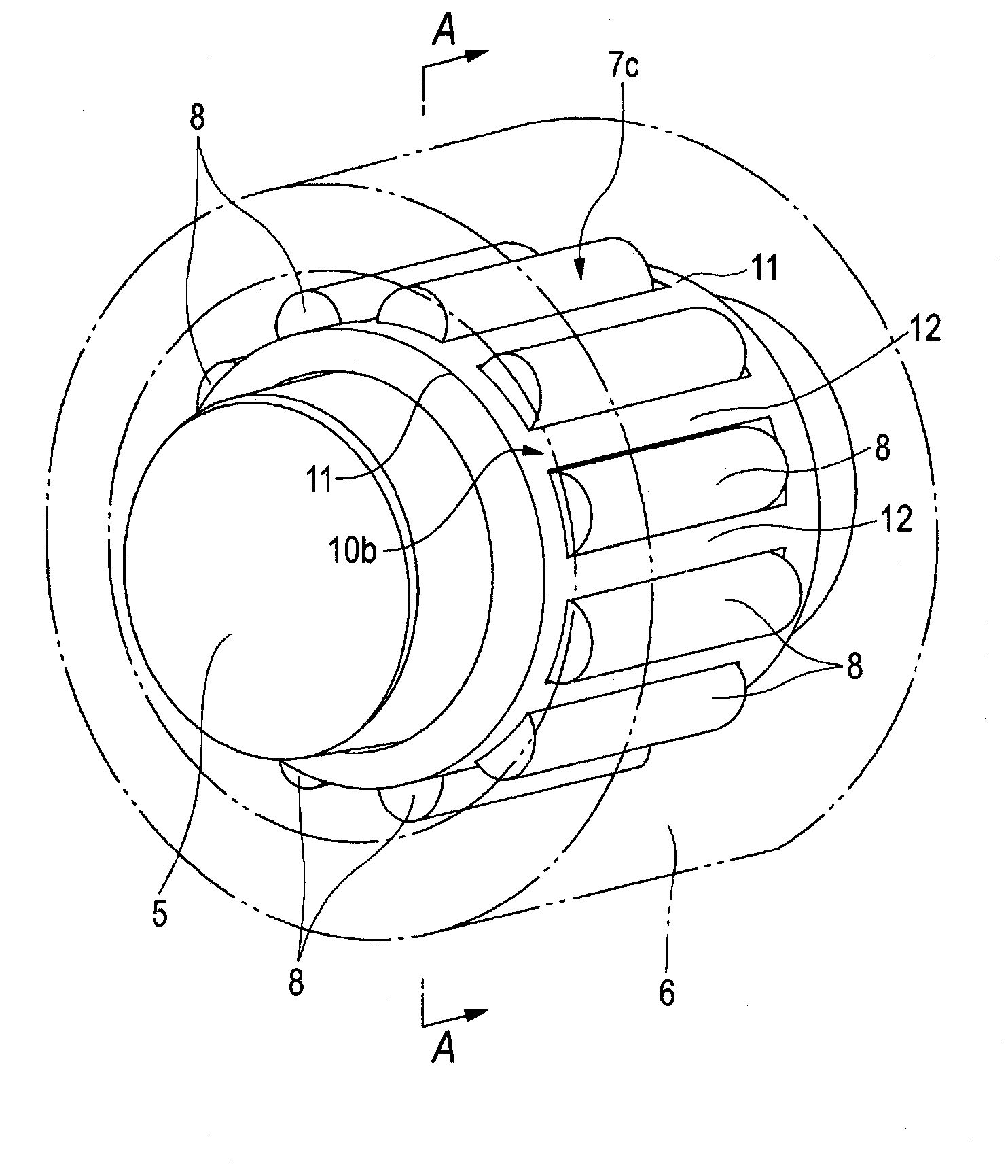
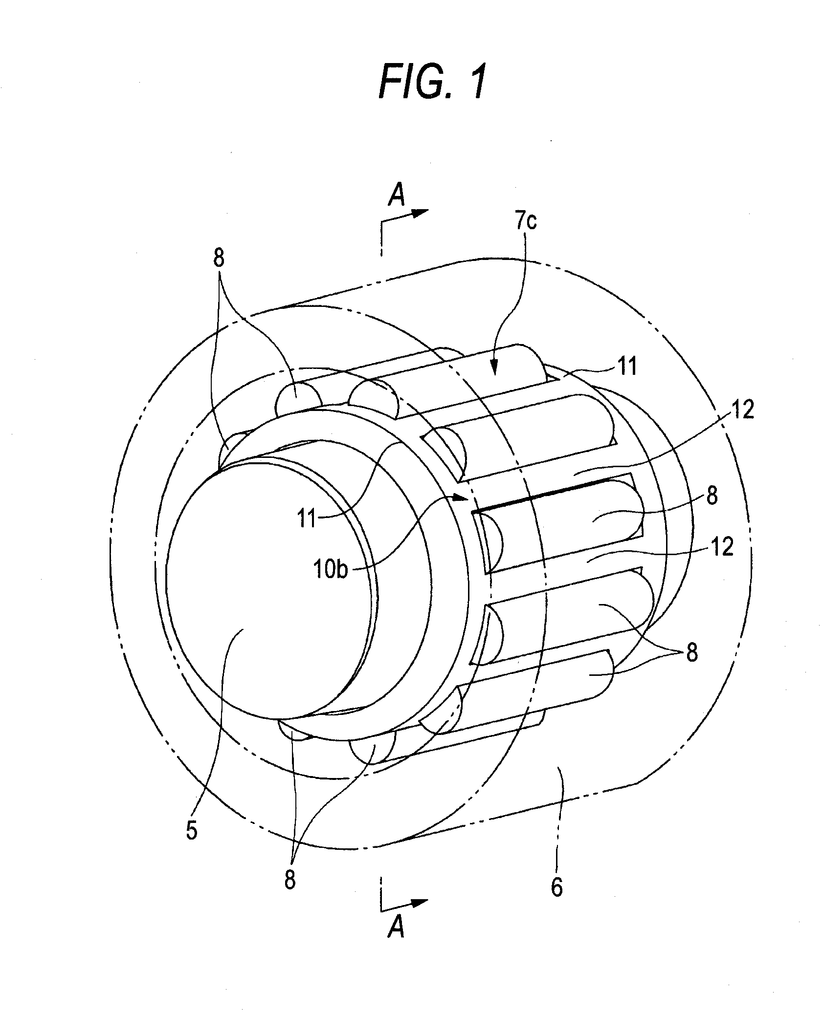
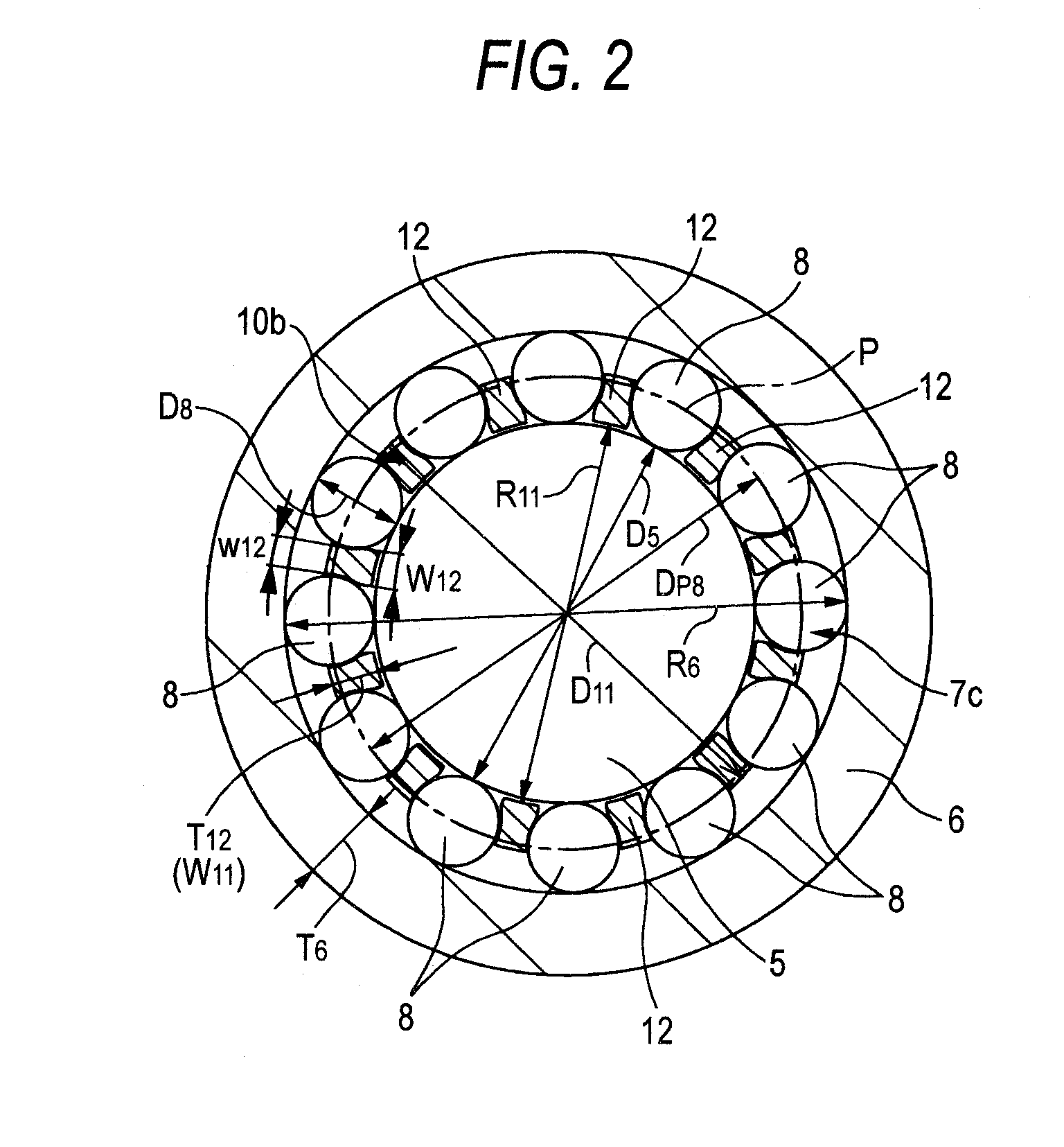
[0063]FIGS. 1 to 2 show Embodiment 1 of the invention. Note that a feature of this embodiment relates to the construction of a radial needle bearing 7c for rotatably supporting a tappet roller 6 on the periphery of a support shaft 5. Since the construction and function of the embodiment excluding the radial needle bearing 7c which includes where both end portions of the support shaft 5 are supported and fixed to support wall portions 4, 4 (refer to FIGS. 18 to 20) of a rocker arm 3 are similar to those of the conventional constructions shown in FIGS. 18 to 20, the repetition of similar illustrations and descriptions will be omitted or simplified, so that characteristic portions of the embodiment will mainly be described below.

[0064]In the case of this embodiment, 12 needles 8, 8 which make up the radial needle bearing 7c are held in such a manner as to freely roll by a basket-shaped cage 10b. This cage 10b is such as to be produced integrally by injection molding a synthetic resin a...

embodiment 2

[0070]FIGS. 3 to 4 show Embodiment 2 of the invention. In the case of this embodiment, a pair of rim portions 11a, 11a and pillar portions 12a, 12a which are provided between both the rim portions 11a, 11a, which both make up a cage 10c, are disposed radially outwards relative to a pitch circle P of respective needles 8, 8. A width dimension of a radially outward end portion of the respective pillar portions 12a, 12a is made larger than a width dimension of a portion which lies closer to an inside diameter side thereof, so that an interval between circumferential edges at an outside diameter side end portion of the pillar portions 12a, 12a which are adjacent to each other in the circumferential direction is made sufficiently smaller than an outside diameter of the respective needles 8, 8. In addition, outer circumferential edges of both the rim portions 11a, 11a and outer circumferential side surfaces of the pillar portions 12a, 12a which are adjacent to each other in the circumfere...

embodiment 3

[0074]FIGS. 6 to 7 show Embodiment 3 of the invention. Note that a feature of this embodiment relates to the construction of a radial needle bearing 7d for rotatably supporting a tappet roller 6 on the periphery of a support shaft 5. Since the construction and function of the embodiment excluding the radial needle bearing 7d which includes where both end portions of the support shaft 5 are supported and fixed to support wall portions 4, 4 (refer to FIGS. 18 to 20) of a rocker arm 3 are similar to those of the conventional constructions shown in FIGS. 18 to 20, the repetition of similar illustrations and descriptions will be omitted or simplified, so that characteristic portions of the embodiment will mainly be described below.

[0075]In the case of this embodiment, 12 needles 8, 8 which make up the radial needle bearing 7d are held in such a manner as to freely roll by a basket-shaped cage 10d. This cage 10d is such as to be produced by blanking and bending a sheet material of an iron...


PUM


Abstract

As this radial needle bearing 7c, a radial needle bearing is used which includes a cage 10b. Respective pillar portions 12, 12 which make up the cage 10b are disposed more radially inwards than a circle pitch of respective needles 8, 8. In addition, the needles 8, 8 which are adjacent to each other in a circumferential direction are caused to approach each other, so as to secure the number of such needles 8, 8. As a result, no large bending stress is applied to a tappet roller 6 without increasing the thickness of the tappet roller 6.

Description

TECHNICAL FIELD[0001]A cam follower apparatus according to the present invention is used as a component of an intake and exhaust valve driving system of an engine which transforms rotations of a camshaft into reciprocating oscillating motions of rocker arms.BACKGROUND ART[0002]With a view to realizing a reduction in friction in an interior of an engine so as to reduce the fuel consumption rate, it is general practice to utilize a cam follower apparatus which incorporates therein a tappet roller in a portion where rotations of a camshaft which are in synchronous with those of a crankshaft are transformed into reciprocating motions of intake valves and exhaust valves. FIGS. 18 to 20 show an example of a cam follower apparatus with a tappet roller incorporated therein which is described in Patent Document No. 1.[0003]A rocker arm 3 is provided which faces a cam 2 fixed (generally, integrally formed with) on to a camshaft 1 which rotates in synchronous with a crankshaft of an engine and...

Claims


Application Information

Patent Timeline
Patent Type & Authority Applications(United States)
IPC IPC(8): F01L1/18F16C19/24F01L1/14
CPCF01L1/146F01L1/18F01L1/181F01L1/20F01L2101/00F01L2101/02F16C2240/80F01L2105/02F01L2820/01F16C13/006F16C33/46F16C33/54F16C2240/40F01L2103/00F16C19/466F16C33/543F16C2360/18F01L2305/02F01L2301/02F01L2301/00F01L2303/00
Inventor WATANABE, MAKOTOKADOKAWA, SATOSHI
Owner NSK LTD
Why Eureka
Try Eureka