Electromagnetic stirrer for continuous casting solidification end and dynamic control method thereof

An electromagnetic stirrer and solidification end technology, which is applied in the field of steel continuous casting production, can solve the problems of insufficient stirring capacity of the electromagnetic stirrer, unstable electromagnetic stirring effect at the end of the continuous casting billet, etc., and achieves low power consumption, stable magnetic field and high efficiency. high effect

Active Publication Date: 2015-07-08
NORTHEASTERN UNIV
View PDF8 Cites 12 Cited by
  • Summary
  • Abstract
  • Description
  • Claims
  • Application Information

AI Technical Summary

Problems solved by technology

[0006] The purpose of the present invention is to solve the defect of insufficient stirring ability of the electromagnetic stirrer at the solidification end of the large-section continuous casting billet and the unstable electromagnetic stirring effect at the end of the continuous casting billet, and propose an electromagnetic stirrer with a strong magnetic field and low energy consumption and its dynamic The adjustment method can effectively drive the flow of molten steel in the two-phase region of the continuous casting slab, promote the redistribution of dendrites and molten steel enriched in solute elements, reduce the central segregation of the continuous casting slab, and stabilize the internal quality of the casting slab

Method used


Image

  • Electromagnetic stirrer for continuous casting solidification end and dynamic control method thereof
  • Electromagnetic stirrer for continuous casting solidification end and dynamic control method thereof
  • Electromagnetic stirrer for continuous casting solidification end and dynamic control method thereof

Examples


Embodiment Construction

[0029] The present invention will be further described in detail below with reference to the drawings and specific embodiments.

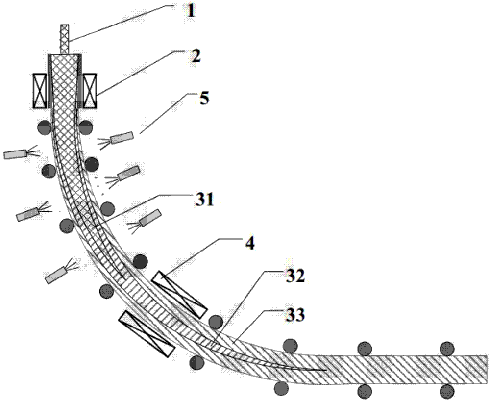
[0030] figure 1 It is a schematic diagram of the bloom continuous casting process of the present invention. The high-temperature liquid steel enters the mold 2 through the immersion nozzle 1 for primary cooling. At this time, it is in the liquid phase zone 31. After cooling, a billet 33 with a certain thickness is formed on the surface and pulled from the mold 2 After entering the secondary cooling zone, the second cooling is carried out under the action of spraying water from the nozzle 5, and the continuous casting billet 3 billet shell 33 is continuously thickened, the liquid phase in the liquid core gradually disappears, and the liquid cavity becomes the two-phase zone 32. The billet with a certain thickness of the billet shell 33 passes through the electromagnetic stirrer 4 at the end of the solidification, and generates an induced electromagnetic ...


PUM


Abstract

Disclosed are an electromagnetic stirrer for a continuous casting solidification end and a dynamic control method thereof. The electromagnetic stirrer for the continuous casting solidification end comprises an inner cylinder and an outer cylinder, wherein the inner cylinder is provided with a continuous casting billet, a direct current electromagnetic body is arranged between the inner cylinder and the outer cylinder, the direct current electromagnetic body is provided with an annular iron core with a salient pole and a coil which surrounds the annular iron core, the direct current electromagnetic body is driven by a drive device to rotate around the inner cylinder, an alternating magnetic field is formed in the continuous casting billet, and then an induced current is induced in the continuous casting billet, and the induced current and the alternating magnetic field interact and generate electromagnetic force so as to drive steel liquid in two phase areas to flow, accelerate redistribution of enriched solute and treelike crystals, and improve internal quality of the continuous casting billet. The dynamic control method of the electromagnetic stirrer for the continuous casting solidification end guarantees that a current stirring parameter is equivalent to the best stirring parameter so as to obtain the best stirring effects and stabilize the internal quality of the continuous casting billet.

Description

Technical field [0001] The invention relates to the field of steel continuous casting production, in particular to an electromagnetic stirrer for large-section square (round) billets in continuous casting production and a dynamic control method thereof. Background technique [0002] In the production process of steel continuous casting, due to the difference in solubility of solute elements in the solid phase and the liquid phase and the diffusion of the liquid phase, the solute elements are continuously excluded from the solid phase and enriched in the liquid phase. During the solidification process, the continuous casting slab is subjected to external forces such as thermal buoyancy, thermal shrinkage, and bulge deformation between the rolls to force the liquid phase to flow, causing the liquid phase rich in segregation elements to gather in the center of the slab, and finally form center segregation and center shrinkage. Holes are particularly serious on large-section cast sla...

Claims


Application Information

Patent Timeline
Patent Type & Authority Applications(China)
IPC IPC(8): B22D11/115B22D11/16
Inventor 朱苗勇姜东滨王卫领罗森刘航
Owner NORTHEASTERN UNIV
Why Eureka
Try Eureka