Common-current collector plate group with positive plates opposite to negative plates and common-current collector module battery

A technology of positive and negative pole pieces and fluid modules, which is applied in the field of positive and negative pole pieces facing common collector fluid plate groups and common fluid module batteries, which can solve the problem of battery manufacturing yield, battery service life, battery pole piece and battery life. It is difficult to ensure the consistency of the unit, the number of connected parts of the battery pack is large, and the charge and discharge efficiency is reduced, so as to improve the adaptability to high temperature environment, shorten the battery life, and improve the high current charge and discharge capacity.

Inactive Publication Date: 2009-10-14
SHANGHAI JIAO TONG UNIV
View PDF1 Cites 10 Cited by
  • Summary
  • Abstract
  • Description
  • Claims
  • Application Information

AI Technical Summary

Problems solved by technology

Therefore, this grouping method has defects such as a large number of connected parts of the battery pack, large connection resistance, increased cost, and large volume and weight, which further reduces the functional density and energy density of the battery pack compared with single batteries, and further increases the cost. The performance is further reduced, and the charge and discharge efficiency is further reduced
[0004] After searching the literature of the prior art, it is found that the Chinese patent publication number CN1780040, the publication date is 2006.05.31, the patent name is: new power battery unit and integrated battery pack, the patent reads as: "new power battery unit and integrated The battery pack, the battery unit includes a positive plate 1, a negative plate 2, a plate separator 3, an electrolyte and a sealing coat 4, the positive plate 1 and the negative plate 2 are stacked together and separated by the plate separator 3, and then sealed with a sealing coat 4 Up, there is an electrolyte stored in the sealed jacket 4, the positive plate 1 and the negative plate 2 are composed of an electrochemical material layer 5 and a conductive skeleton 6, and an electrode piece 7 protrudes from the top of the conductive skeleton 6 on the positive plate 1 and the negative plate 2 , the electrode sheets 7 on all the positive plates 1 are arranged and distributed on one side and connected to form a positive electrode collector 8, and the electrode sheets 7 on all the negative electrode plates 2 are arranged on the other side and connected to form a negative electrode collector 9, the positive electrode collector 8 and the negative current collector 9 are respectively located at the two ends of the battery and its top protrudes from the outside of the sealing jacket 4. Its disadvantage is that the connection of the battery unit requires a connecting piece, which may be damaged if it is welded as described in this patent. There are many diaphragms, connectors, and many welding processes, and it is difficult to guarantee the battery manufacturing yield, battery life, consistency of battery pole pieces and battery cells

Method used


Image

  • Common-current collector plate group with positive plates opposite to negative plates and common-current collector module battery
  • Common-current collector plate group with positive plates opposite to negative plates and common-current collector module battery
  • Common-current collector plate group with positive plates opposite to negative plates and common-current collector module battery

Examples


Embodiment Construction

[0030] The embodiments of the present invention are described in detail below in conjunction with the accompanying drawings: this embodiment is implemented on the premise of the technical solution of the present invention, combining detailed implementation methods and specific operating procedures, but the scope of protection of the present invention is not limited to the following Example.

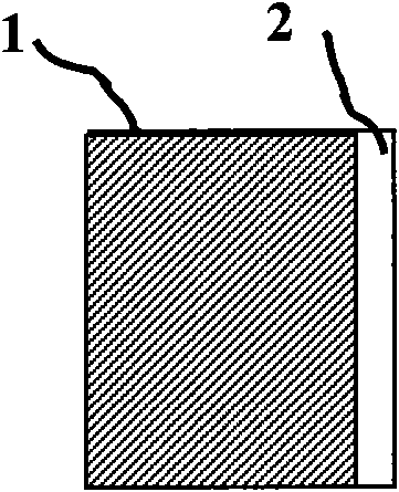
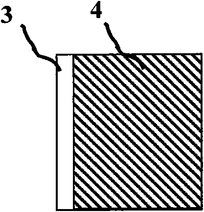
[0031] Such as Figure 1 to Figure 6As shown, the present embodiment relates to a positive and negative plate opposite common current collector electrode plate group, including a number of positive plates 1, negative plates 4 and current collectors 6 in which the number of positive plates 1 is increased by one, and the positive plate 1 has a Conductive substrate exposed segment 2, negative electrode sheet 4 has conductive substrate exposed segment 3 at one end thereof, and the conductive substrate exposed segment 2 of all positive electrode sheets 1 is connected to one side of current col...


PUM


Abstract

The invention relates to a common-current collector plate group with positive plates opposite to a negative plates and a common-current collector module battery, belonging to the technical field of battery. One end of the positive plate of the common-current collector plate group with the positive plate opposite to the negative plate is provided with a naked section of conductive substrate and one end of the negative plate is provided with a naked section of conductive substrate; the naked sections of conductive substrates of all the positive plate are respectively connected with one side of a current collector, and the naked sections of all the conductive substrates of the negative plate are respectively connected with the other side of the current collector; the positive electrode of the module battery penetrates through a sealed shell and is connected with the positive plate group; the negative electrode of the module battery penetrates through a sealed shell and is connected with the negative plate group; all the positive plates are respectively wrapped by a membrane; the common-current collector plate group with the positive plates opposite to the negative plates is arranged between the positive plate group and the negative plate group in sequence; all the positive plates are respectively distributed between adjacent negative plates; and adjacent monomer batteries have a common current collector. The common-current collector plate group has simple structure and long service life, greatly improves large-current charging-discharging capability, charging-discharging efficiency, thermal environment adaptability and anti-vibration capability of the battery.

Description

technical field [0001] The invention relates to a product in the field of battery technology, in particular to a positive and negative pole plate opposite common collector electrode plate group and a common collector module battery thereof. Background technique [0002] The single cells of the existing structure all have separate sealed shells. In addition to the positive and negative electrodes, diaphragms, and electrolytes, there are tabs, current collectors, anti-rotation devices, etc. inside the square single cells, and the proportion of inert substances is large. , complex structure, many welding processes, long conductive path, there are defects of large internal resistance of single battery, large number of parts, high cost, large weight and volume, poor reliability, low charge and discharge efficiency of single battery, its functional density, energy density much lower than the theoretical density. In addition, the current density distribution of the positive and ne...

Claims


Application Information

Patent Timeline
Patent Type & Authority Applications(China)
IPC IPC(8): H01M4/00H01M4/02H01M2/26H01M4/64H01M10/48H01M10/00H01M10/04H01M10/50H01M10/44H01M2/02H01M10/613H01M10/65H01M50/528H01M50/531
CPCY02E60/12Y02E60/10Y02P70/50
Inventor 杨林羌嘉曦陈自强秦俊
Owner SHANGHAI JIAO TONG UNIV
Why Eureka
Try Eureka