
Optical concatenation for field sequential stereoscpoic displays

a stereoscopic display and optical concatenation technology, applied in the direction of color television details, instruments, electrical devices, etc., can solve the problems of average viewers' perceptible onscreen visual anomalies, and achieve the effect of facilitating stereoscopic image transmission and reducing “judder” or other adverse visual effects

Inactive Publication Date: 2008-10-02
REAID INC
View PDF8 Cites 91 Cited by
  • Summary
  • Abstract
  • Description
  • Claims
  • Application Information

AI Technical Summary

Benefits of technology

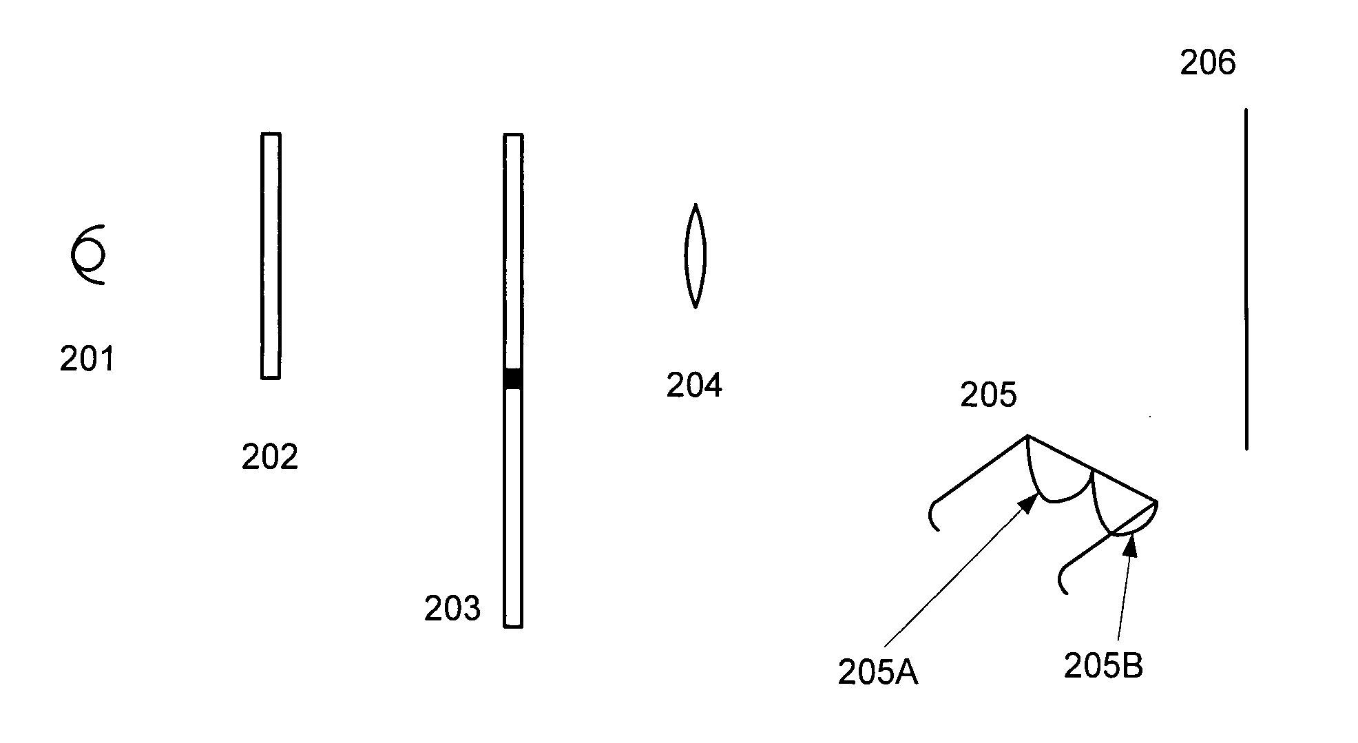
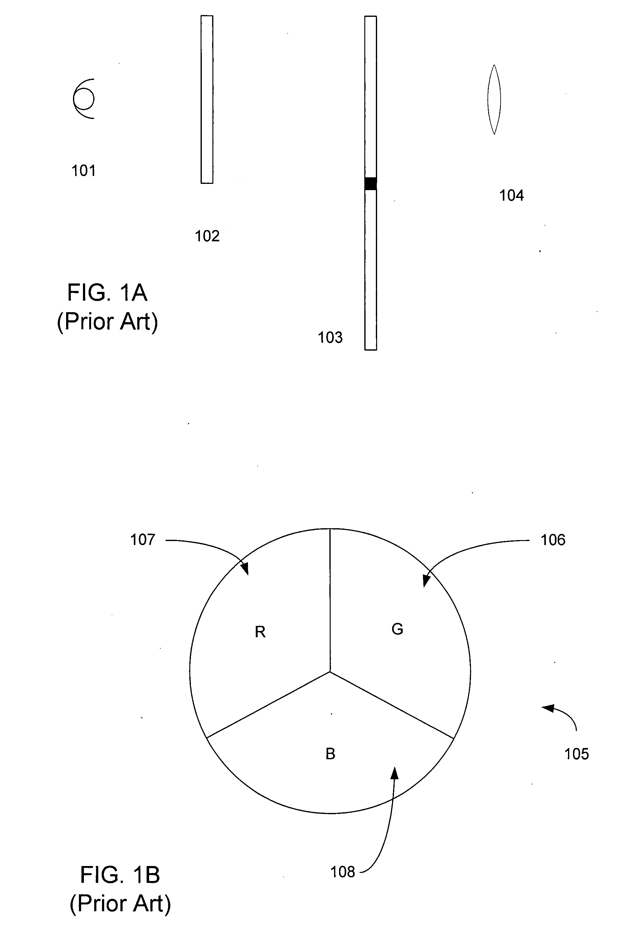
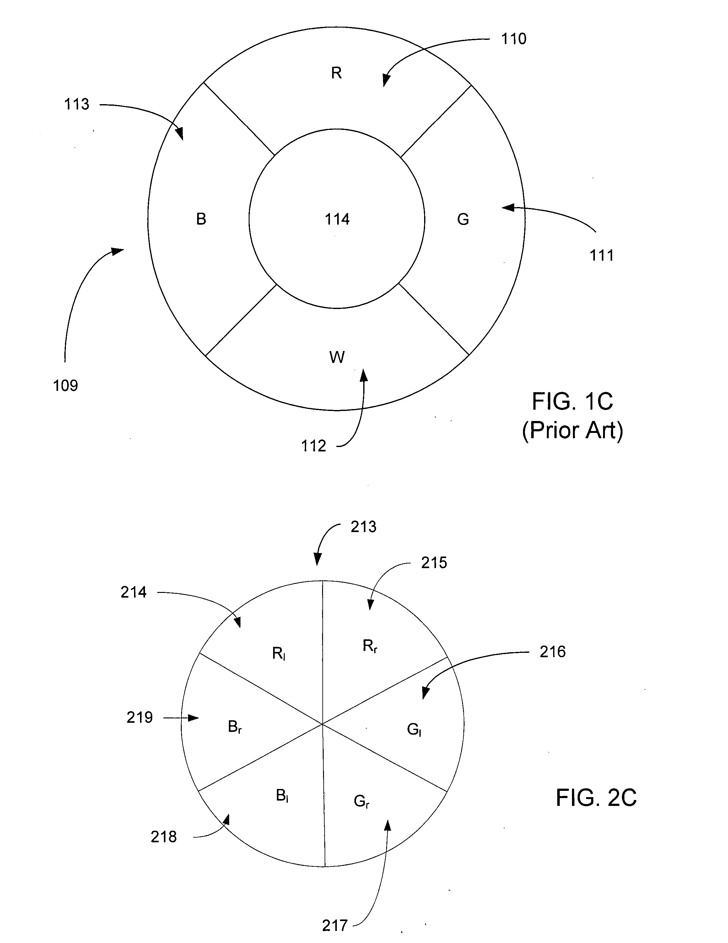
[0008]According to one aspect of the present design, there is provided a device used in projecting or transmitting stereoscopic images is provided. The device includes a multi-section light emitter, such as a “color wheel or a series of light emitting diodes (LEDs) configured to emit light energy in multiple sections. Each section of light energy has an optical attribute associated therewith, such as color. Light energy projected in at least two sequential sections by the multi-section light emitter provides light energy having identical optical attributes, such as identical colors (red, green, or blue) but different perspective views associated with each sequential section, where the same optical attributes being employed in adjacent sections is referred to as “concatenation.” Different polarization attributes or polarization axis orientations may be employed within each section to facilitate stereoscopic image transmission and such concatenation in many cases reduces “judder” or other adverse visual effects. Light emitting diodes (LEDs) illuminated in an additive color sequence may be employed in place of a spinning color wheel.

Problems solved by technology

The challenge with these types of devices is minimizing the adverse effects, including but not limited to visual effects known as “judder.” Judder is an artifact resulting from non-precisely temporally matched frames, such as interlaced frames in a stereoscopic projected image or movie.
Mismatching or imperfect timing can result from various sources, such as power interruptions, timing mismatches, frame loading errors, among other issues, and results in onscreen visual anomalies perceptible by the average viewer.

Method used


Image

  • Optical concatenation for field sequential stereoscpoic displays
  • Optical concatenation for field sequential stereoscpoic displays
  • Optical concatenation for field sequential stereoscpoic displays

Examples


Embodiment Construction

[0025]The present design combines both color and perspective encoding in one embodiment using a spinning color / polarization wheel, or in another embodiment LEDs or similar additive color techniques are employed to illuminate the image engine in a color sequence. In yet another embodiment, active eyewear is used for the occlusion approach to image selection. Polarization may be employed, and three variants of polarization may be used: linear, circular, and achromatic circular. Subfield concatenation can be varied to further enhance performance by reducing undesirable effects such as stereoscopic motion judder. Accordingly, there are many permutations of this design all generally following the basic principles, and a person versed in the art will understand that changing these polarizations is relatively trivial once the general principles enunciated herein are understood, and numerous such variations will fall within the scope of these teachings.

[0026]The basic idea of the present de...


PUM


Abstract

A device used in projecting or transmitting stereoscopic images is provided. The device includes a multi-section light emitter, such as a “color wheel or a series of light emitting diodes (LEDs) configured to emit light energy in multiple sections. Each section of light energy has an optical attribute associated therewith, such as color. Light energy projected in at least two sequential sections by the multi-section light emitter provides light energy having identical optical attributes, such as identical colors (red, green, or blue) but different perspective views associated with each sequential section, where the same optical attributes being employed in adjacent sections is referred to as “concatenation.” Different polarization attributes or polarization axis orientations may be employed within each section to facilitate stereoscopic image transmission and such concatenation in many cases reduces “judder” or other adverse visual effects.

Description

[0001]This application is being filed concurrently with U.S. patent application Ser. No. ______, entitled “Color and Polarization Timeplexed Stereoscopic Display Apparatus,” inventor Lenny Lipton, the entirety of which is incorporated herein by reference.BACKGROUND OF THE INVENTION[0002]1. Field of the Invention[0003]The present invention relates to the art of concatenating color and perspective fields for reducing temporal artifacts in a stereoscopic display, and more specifically to techniques useful for single image engine displays using field sequential color.[0004]2. Description of the Related Art[0005]Various types of stereoscopic displays are currently available, and operation of such displays is constantly being evaluated and improved to enhance the stereoscopic viewing experience. Certain projection displays employ what can be called the “additive color timeplex” method. Such a colorplexing display can be combined with time multiplexing of perspective views for stereoscopic...

Claims


Application Information

Patent Timeline
IPC IPC(8): H04N15/00G02B30/25H04N13/363
CPCH04N13/0422H04N13/0431H04N13/0434H04N13/0459H04N13/337H04N13/324H04N13/334H04N13/363
Inventor LIPTON, LENNY
Owner REAID INC
Learn More