[0010] Thus, it would be advantageous to develop systems and methods for reinforcing a
heart valve annulus or other body structure using an annuloplasty device that can be adjusted within the body of a patient in a minimally invasive or non-invasive manner. In an embodiment, an adjustable annuloplasty device includes a body member configured to conform at least partially to a
cardiac valve annulus. The body member includes a shape memory material configured to transform from a first shape to a second shape in response to being heated. The annuloplasty device further includes a thermally insulative material at least partially covering said body member and a thermally conductive material extending into said thermally insulative material. The thermally conductive material is configured to communicate
thermal energy to the body member. The thermally conductive material can be configured as an imaging marker and can include a radiopaque material. The annuloplasty device further includes a suturable material at least partially covering said thermally insulative material. The thermally conductive material can be disposed at least partially over said suturable material and can provide indicia of one or more valve
commissure locations after said annuloplasty device is implanted on or near a
heart valve annulus. The thermally conductive material can include at least one of a metallic wire or a metallic ribbon and the body member can be selected from a variety of shapes including, for example, ring shaped, C-shaped and D-shaped.
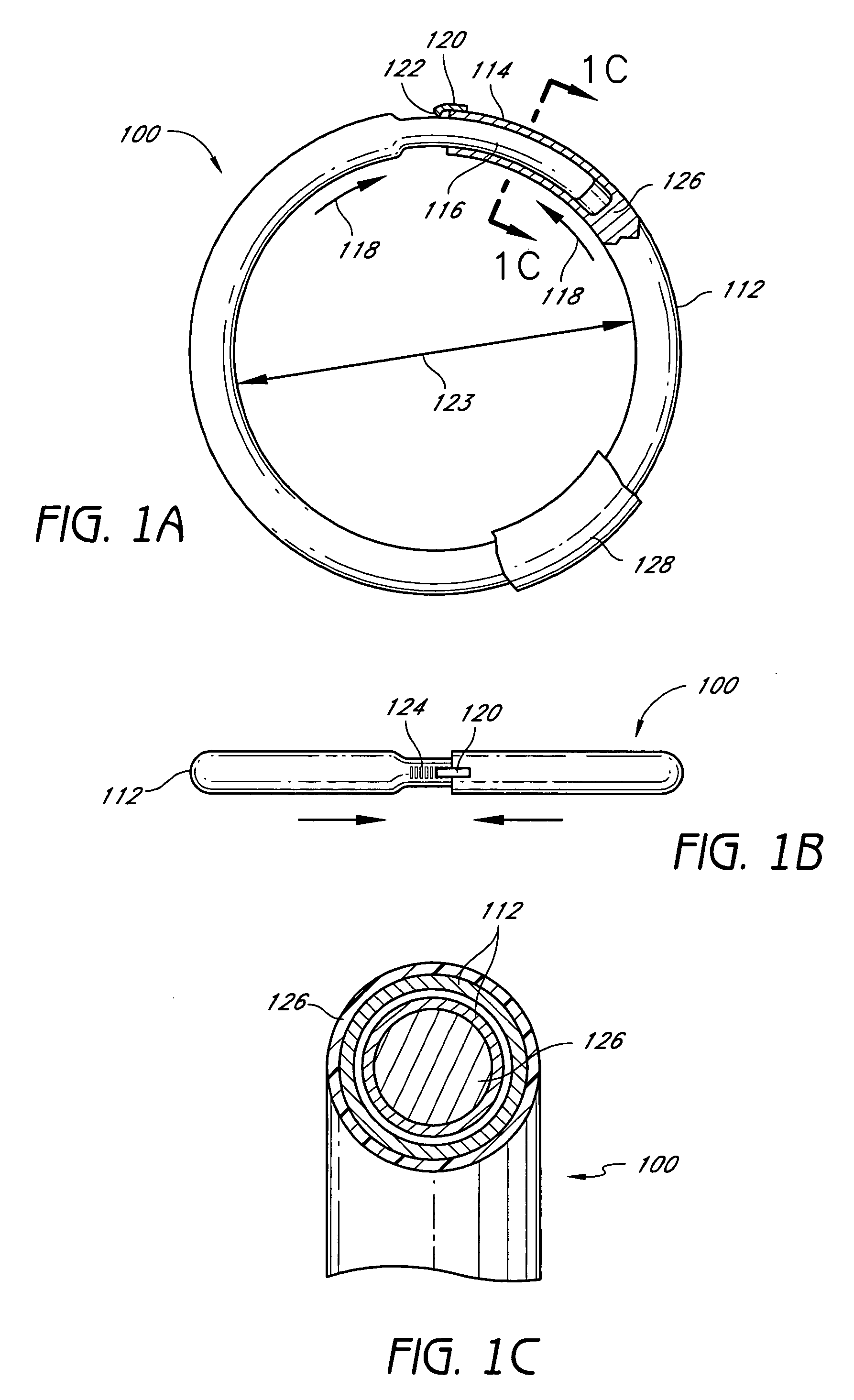
[0015] In another embodiment, an adjustable annuloplasty ring includes a tubular member configured to be attached to or near a cardiac valve annulus. The tubular member includes a receptacle end and an insert end configured to couple with said receptacle end of said tubular member such that said tubular member substantially forms a shape of a ring. The insert end is configured to move with respect to said receptacle end to change a circumference of said ring. The tubular member can further include a shape memory material configured to change, after implantation in a patient's body, from a first shape to a second shape in response to an
activation energy, wherein said
shape change causes said change in the circumference of said ring. The tubular member can further include an
energy absorption enhancement material disposed within said tubular member. The
energy absorption enhancement material facilitates transfer of heat to said shape memory material. The
energy absorption enhancement material can be further disposed on an outer surface of said tubular member. The tubular member can further include a
ratchet member configured to allow said insert end to move predominantly in a first direction with respect to said receptacle end, and to
resist movement in a second, opposite direction. The annuloplasty ring can be ring shaped, C-shaped, D-shaped, or another shape.
[0016] In another embodiment, an adjustable annuloplasty ring includes a body member configured to be attached to or near a cardiac valve annulus. The body member includes a first end and a second end configured to couple with said first end of said body member such that said body member substantially forms a shape of a ring. The second end is configured to move with respect to said first end to change a circumference of said ring. The body member can further include a shape memory material configured to change, after implantation in a patient's body, from a first shape to a second shape in response to an
activation energy, wherein said
shape change causes said change in the circumference of said ring. The body member can further include an energy absorption enhancement material that facilitates transfer of heat to said shape memory material. The body member can further include a
ratchet member configured to allow said second end to move predominantly in a first direction with respect to said first end, and to
resist movement in a second, opposite direction. The annuloplasty ring can be ring shaped, C-shaped, D-shaped, or another shape.
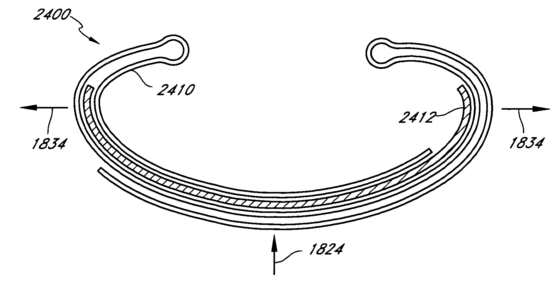
[0021] In another embodiment, an annuloplasty device configured to support a heart valve includes an anterior portion, a posterior portion, and two lateral portions corresponding to intersections of said anterior portion and said posterior portion. The annuloplasty device has a first shape in a first configuration and a second shape in a second configuration. The annuloplasty device is configured to transform from said first configuration to said second configuration in response to a first
activation energy applied thereto. The transformation is configured to reduce a distance between said anterior portion and said posterior portion without substantially decreasing a distance between said two lateral portions. The annuloplasty device can also include one or more imaging markers that can include, for example, radiopaque markers. The transformation can be further configured to increase said distance between said two lateral portions.
[0024] In certain embodiments, the annuloplasty device further includes a first shape memory band that extends at least partially along said anterior and posterior portions. The first shape memory band loops back on itself in a curvilinear configuration such that portions of said first shape memory band overlap one another. The first shape memory band can be configured to change its length in response to said first activation energy such that said overlapping portions slide with respect to one another to change said annuloplasty device from said first configuration to said second configuration. The annuloplasty device can further include a second shape memory band at least partially disposed between or adjacent to said overlapping portions of said first shape memory band. The second shape memory band can be configured to respond to a second activation energy to transform said annuloplasty device from said second configuration to a third configuration. The annuloplasty device in said third configuration can have a reduced distance between said anterior portion and said posterior portion as compared to said second shape. Alternatively, the annuloplasty device in said third configuration can have an increased distance between said anterior portion and said posterior portion as compared to said second shape. At least one of said first activation energy and said second activation energy can include a
magnetic field,
acoustic energy,
radio frequency energy, or another form of energy. The first shape memory band can change to a first
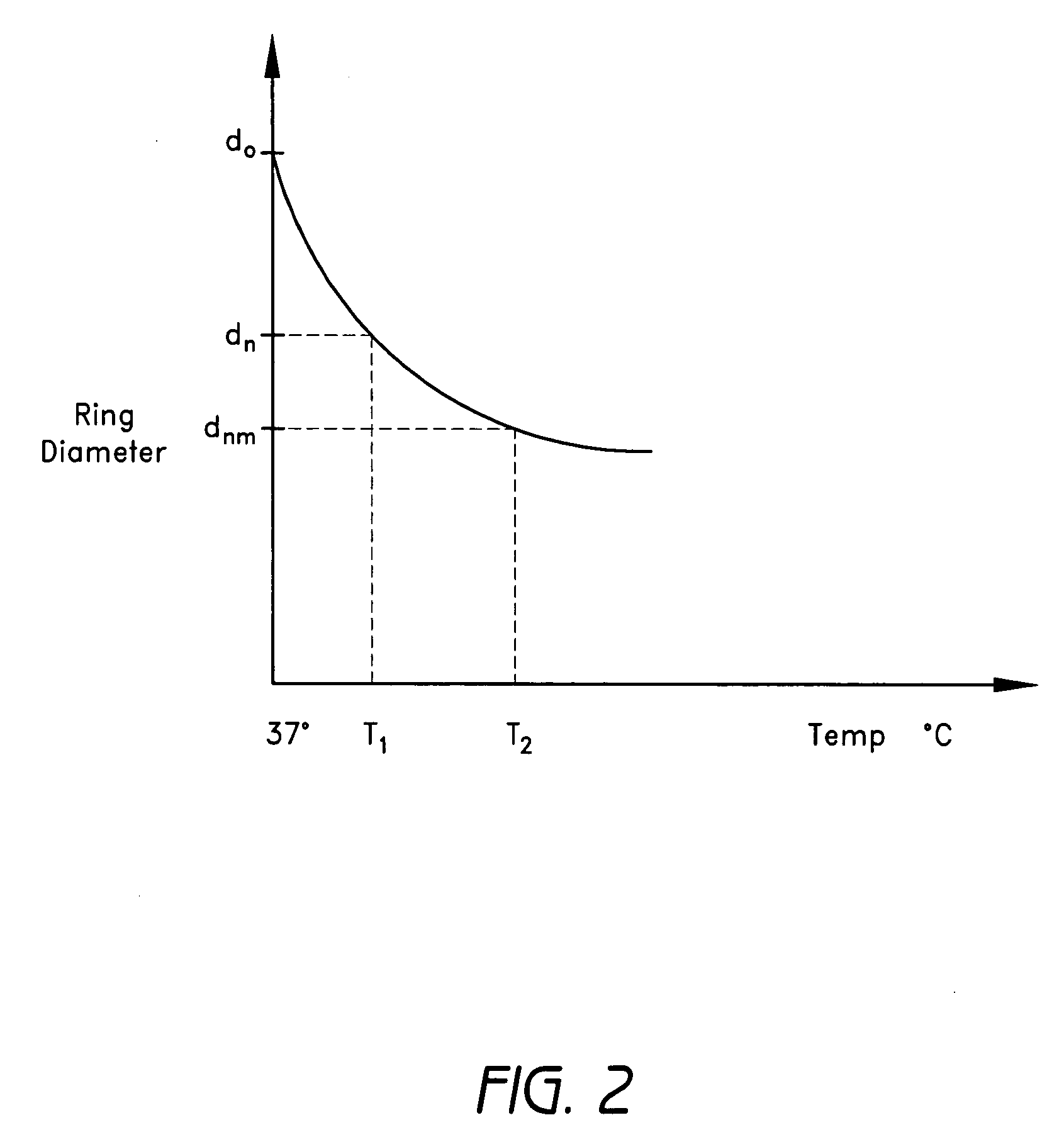
activation temperature in response to said first activation energy, wherein said second shape memory band changes to a second
activation temperature in response to said second activation energy.

