Extreme ultraviolet light source

a technology of ultraviolet light and light source, which is applied in the field of extreme ultraviolet light source, can solve the problems of difficult to obtain sufficient transmission of optical materials at this wavelength and high optical quality, and the limited optical components of light at wavelengths below 157 nm, and achieve the effect of improving the electrode configuration

Inactive Publication Date: 2005-12-06
ASML NETHERLANDS BV
View PDF59 Cites 143 Cited by
  • Summary
  • Abstract
  • Description
  • Claims
  • Application Information

AI Technical Summary

Benefits of technology

[0012]This prototype devices actually built and test by Applicants convert electrical pulses (either positive or negative) of about 10 J of stored electrical energy per pulse into approximately 50 mJ of in-band 13.5 nm radiation emitted into 2π steradians. Thus, these tests have demonstrated a conversion efficiency of about 0.5%, Applicants estimate that they can collect about 20 percent of the 50 mJ 13.5 nm radiation so that this demonstrated collected energy per pulse will be in about of 10 mJ. Applicants have demonstrated 1000 Hz continuous operation and 4000 Hz short burst operation. Thus, 10 Watt continuous and 40 Watt burst outputs have been demonstrated. Using collection techniques designed by Applicants about half of this energy can be delivered to an intermediate focus distant from the plasma source. Thus providing at least 5 Watts of in band EUV light at the intermediate focus on a continuous basis and at least 20 Watts on a burst basis. Applicants have also shown that the techniques described herein can be applied to provide outputs in the range of 60 Watts at repetition rates of 5,000 Hz or greater. At 2000 Hz, the measured pulse-to-pulse energy stability, (standard deviation) was about 9.4% and no drop out pulses were observed. The electrical circuit and operation of this prototype DPF device is presented along with a description of several preferred modifications intended to improve stability, efficiency and performance.
[0014]The present invention provides a practical implementation of EUV lithography in a reliable, high brightness EUV light source with emission characteristics well matched to the reflection band of the Mo / Si or Mo / Be mirror systems. Tests by Applicants have demonstrated an improved electrode configuration in which the central electrode configuration in which the central electrode is hollow and configured as a cathode. For this configuration the hollow cathode produces its own pre-ionization so special pre-ionization is not needed.

Problems solved by technology

An excimer line exists at 157 nm, but optical materials with sufficient transmission at this wavelength and sufficiently high optical quality are difficult to obtain.
Optical components for light at wavelengths below 157 nm are very limited.
Solid targets have been used, but the debris created by ablation of the solid target has detrimental effects on various components of a system intended for production line operation.
However, none of these systems have so far proven to be practical for production line operation.
Typical prior art plasma focus devices can generate large amounts of radiation suitable for proximity x-ray lithography, but are limited in repetition rate due to large per pulse electrical energy requirements, and short lived internal components.

Method used


Image

  • Extreme ultraviolet light source
  • Extreme ultraviolet light source
  • Extreme ultraviolet light source

Examples


Embodiment Construction

Hot Plasmas

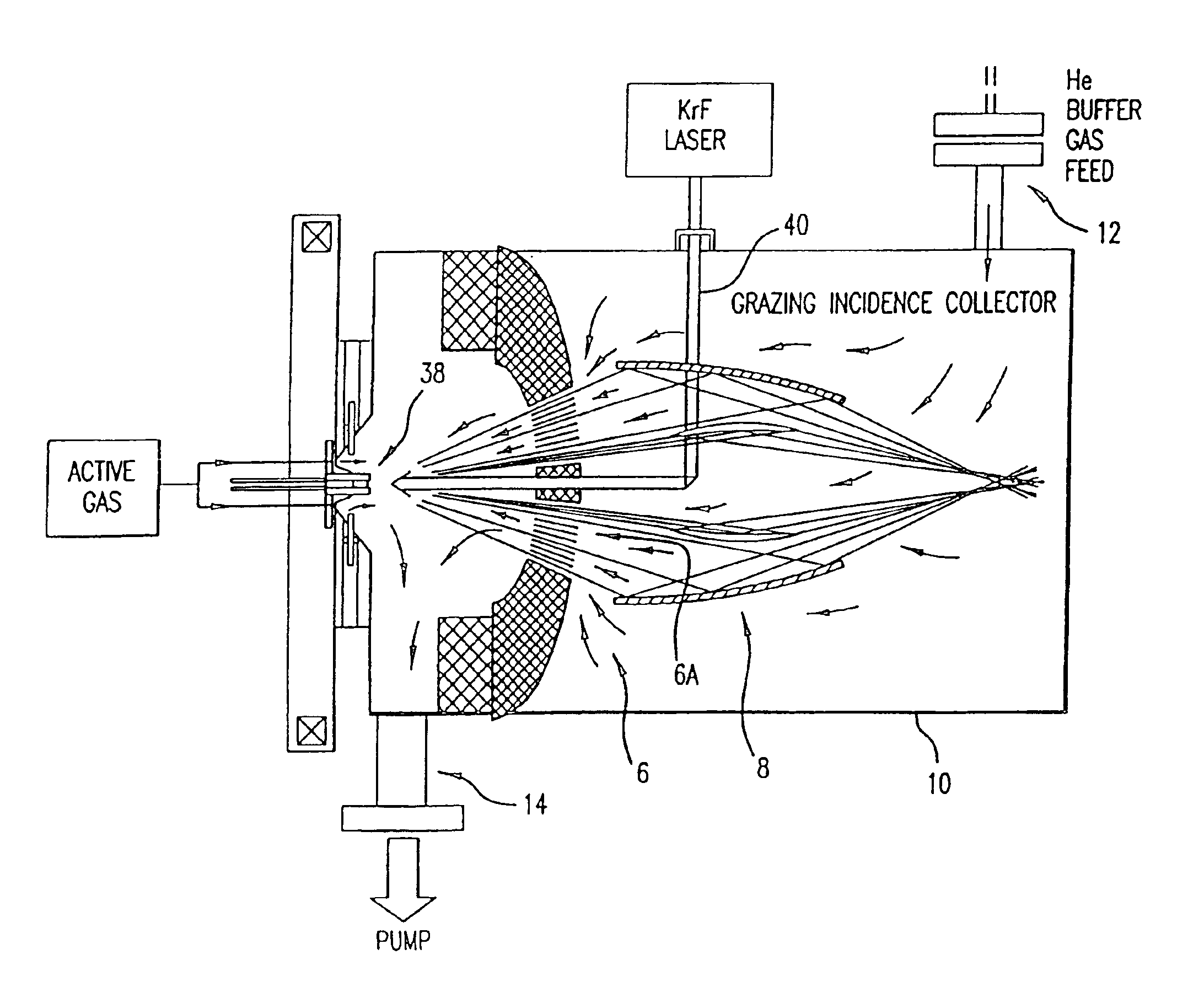
[0060]To produce light in the spectral range of 13-14 nm from plasma requires a very hot plasma corresponding to temperatures of in the range of several thousand degrees Celsius. Plasmas at these temperatures can be created by focusing a very high power (very short pulse) laser beam or a high energy electron beam on the surface of a metal target. It is also possible to produce very hot plasma in a gas with electric discharges using any of several special discharge techniques which focus or pinch the plasma. These techniques included (1) a dense plasma focus technique (2) a regular Z-pinch technique, (3) a hollow cathode Z-pinch and (4) a capillary discharge technique. All of these techniques are discussed in greater detail below. For use as a lithography light source for integrated circuit fabrication the light source and the power supply for it should be capable of continuous, reliable, round-the-clock operation for many billions of pulses. This is because the lithograph...


PUM

PropertyMeasurementUnit
wavelength bandaaaaaaaaaa
wavelengthaaaaaaaaaa
wavelengthsaaaaaaaaaa

Abstract

The present invention provides a reliable, high-repetition rate, production line compatible high energy photon source. A very hot plasma containing an active material is produced in vacuum chamber. The active material is an atomic element having an emission line within a desired extreme ultraviolet (EUV) range. A pulse power source comprising a charging capacitor and a magnetic compression circuit comprising a pulse transformer, provides electrical pulses having sufficient energy and electrical potential sufficient to produce the EUV light at an intermediate focus at rates in excess of 5 Watts. In preferred embodiments designed by Applicants in-band, EUV light energy at the intermediate focus is 45 Watts extendable to 105.8 Watts.

Description

[0001]This application is a continuation-in-part of U.S. Ser. No. 10 / 384,967 filed Mar. 8, 2003, Ser. No. 10 / 189,824 filed Jul. 3, 2002 now U.S. Pat. No. 6,815,700, U.S. Ser. No. 10 / 120,655 filed Apr. 10, 2002, now U.S Pat. No. 6,744,060, U.S. Ser. No. 09 / 875,719 filed Jun. 6, 2001 now U.S. Pat. No. 6,586,757, and U.S. Ser. No. 09 / 875,721 filed Jun. 6, 2001 now U.S. Pat No. 6,566,668, U.S. Ser. No. 09 / 690,084 filed Oct. 16, 2000 now U.S. Pat. No. 6,566,667 ; and claims the benefit of patent application Ser. No. 60 / 422,808 filed Oct. 31, 2002 and patent application Ser. No. 60 / 419,805 filed Oct. 18, 2002; all of which is incorporated by reference herein. This invention relates to high-energy photon sources and in particular highly reliable x-ray and high-energy ultraviolet sources.BACKGROUND OF THE INVENTION[0002]The semiconductor industry continues to develop lithographic technologies, which can print ever-smaller integrated circuit dimensions. These systems must have high reliabili...

Claims


Application Information

Patent Timeline
Patent Type & Authority Patents(United States)
IPC IPC(8): G01J1/00G21K5/00G03F7/20G21K5/02H01L21/027H01S3/00H05G2/00H05H1/06H05H1/24
CPCB82Y10/00G03F7/70033G03F7/70166G03F7/70175G03F7/70916H01S3/005H05G2/003H05G2/008H05H1/06H05G2/005
Inventor MELNYCHUK, STEPHAN T.PARTLO, WILLIAM N.FOMENKOV, IGOR V.OLIVER, I. ROGERNESS, RICHARD M.BOWERING, NORBERTKHODYKIN, OLEHRETTIG, CURTIS L.BLUMENSTOCK, GERRY M.DYER, TIMOTHY S.SIMMONS, RODNEY D.HOFFMAN, JERZY R.JOHNSON, R. MARK
Owner ASML NETHERLANDS BV
Why Eureka
Try Eureka