Proximally Self-Locking Long Bone Prosthesis

a long bone prosthesis and self-locking technology, applied in the field of medical implants, can solve the problems of joint cartilage damage, mechanical pain, eventual destruction of joint cartilage, etc., and achieve the effects of improving the sealing, maintaining the flexibility of the diaphysis, and improving the sealing

Active Publication Date: 2008-10-02
ARTHREX
View PDF21 Cites 21 Cited by
  • Summary
  • Abstract
  • Description
  • Claims
  • Application Information

AI Technical Summary

Benefits of technology

This patent describes a new design for a hip joint replacement device called a femoral implant. One key feature is its use of a special material called nitinol, which can remember its original shape when heated and returns to its previous state if cooled down. When this material is used in the implant it helps improve how well it fits in the patient's body. Another important aspect is the way the implant is locked onto the patient's thigh bone - this makes sure there are no gaps between them where any harmful materials could enter. Overall, these technical improvements make the femoral implant safer and better for patients.

Problems solved by technology

Implantable prostheses like cemented and cementless femoral implants are widely used in orthopedic procedures. These implants help restore function and alleviate symptoms associated with damaged joints. However, there are drawbacks related to each method. Cemented implants offer better initial stability but may result in bone marrow edema and potential complications while cementless implants take longer to recover and may experience bone loss if they fail to properly integrate with the host bone. Another issue relates to preventing periprosthetic infection caused by foreign particles generated during dental extraction surgeries. Previous attempts to address these issues involve applying drugs to the surface of the implant or introducing new surfaces designed to promote cell growth or reduce friction. Shape memory materials like nitinol have also been explored as a possible solution to these challenges.

Method used


Image

  • Proximally Self-Locking Long Bone Prosthesis
  • Proximally Self-Locking Long Bone Prosthesis
  • Proximally Self-Locking Long Bone Prosthesis

Examples


example 1

Finite Element Modeling of a Long-Stemmed Implant

[0074]A computational model of a long-stemmed Nitinol prosthesis was created using finite element modeling techniques. The results warn that long-stemmed prosthetics with Nitinol stems may be susceptible to bending-induced fracture.

[0075]FIGS. 9a and 9b show a finite element model geometries used and designated as “Hip A” and “Hip B” respectively. The material properties for the finite element analyses were assumed to be linear elastic and isotropic. CoCrMo and Nitinol used in these analyses were assumed to follow Hooke's Law, and frictional forces could be neglected since the applied force was much higher than the frictional forces. All finite element models were assumed to be linear and un-cemented. The force(s) transmitted from walking were assumed to be transmitted from the femur into the implant, where the force then was transmitted to the ball. From there, the force was then transmitted into the liner and cup. The force transmit...

example 2

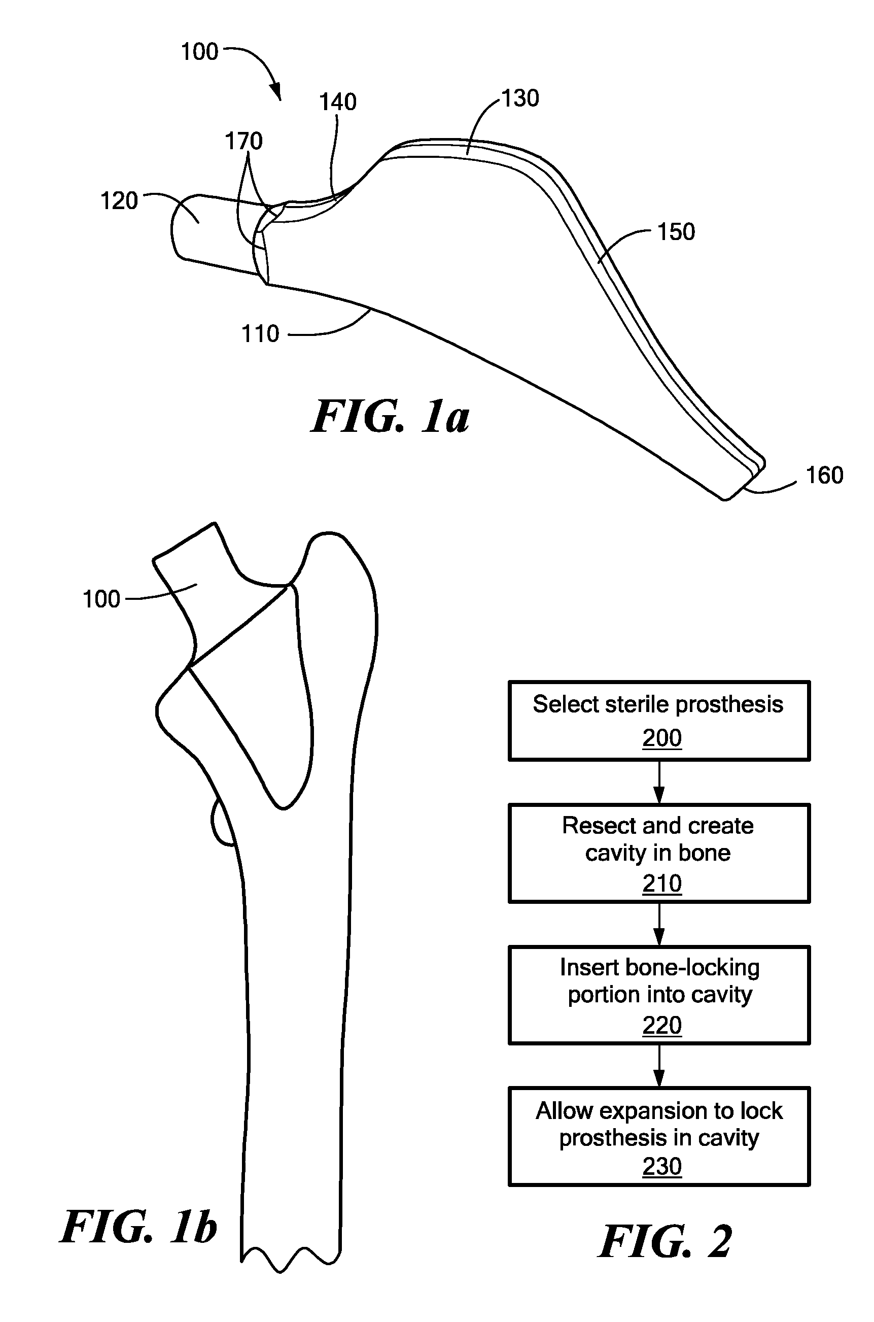
Finite Element Modeling of an Implant According to FIG. 1a

[0082]To confirm the hypothesis that a short-stemmed Nitinol prosthesis 100 with a lateral flare according to FIG. 1a would be sufficiently robust, further finite element modeling was performed to simulate the fatigue endurance strength properties of a short-stemmed prosthesis. A quasi-static analyses was performed with the commercial finite element analysis (FEA) code ABAQUS / Standard version 6.5-1. Three dimensional elements and a large displacement formulation were used. Two material models were used for this report: the first was a Nitinol material model assuming a superelastic response with an Af temperature of 30° C. and a typical stainless steel material with approximately 20% cold work was chosen as a baseline for comparison. Two finite element models were created to examine the effect of mesh refinement on the accuracy of the solution. The number of degrees of freedom for the base model and the fine model were 44853 ...


PUM

PropertyMeasurementUnit
Lengthaaaaaaaaaa
Fractionaaaaaaaaaa
Fractionaaaaaaaaaa

Abstract

A method for arthroplasty includes using a self-locking prosthesis that has a member structured to transfer a load produced by the weight of a patient to a bone. An expandable bone-locking portion that is integral to the member includes a shape-memory material and expands to produce a locking force. A portion of the bone is removed to form an aperture in the bone. The bone-locking portion is inserted into the aperture, and a temperature increase causes a change from a contracted state to an expanded state resulting in expansion of the bone-locking portion so as to contact the inner surface. The expanding is sufficient to create a locking force at the junction between the inner surface and the bone-locking portion of the prosthesis and the majority of the locking force is applied at or above the metaphysis. The length/width ration of the prosthesis may be less than or equal to 5. The resulting reconstructed long-bone may have improved primary and long-term stability.

Description


Claims


Application Information

Patent Timeline
Owner ARTHREX
Why Eureka
Try Eureka