Aerosol Separator; and Method

a technology of separator and aerosol, which is applied in the direction of machine/engine, combustion-air/fuel-air treatment, synthetic resin layered products, etc., can solve the problem of carrying substantial amounts of fine contaminants

Active Publication Date: 2008-10-09
DONALDSON CO INC
View PDF99 Cites 118 Cited by
  • Summary
  • Abstract
  • Description
  • Claims
  • Application Information

AI Technical Summary

Problems solved by technology

In addition, such gas streams also carry substantial am

Method used


Image

  • Aerosol Separator; and Method
  • Aerosol Separator; and Method
  • Aerosol Separator; and Method

Examples


example operation

and Service

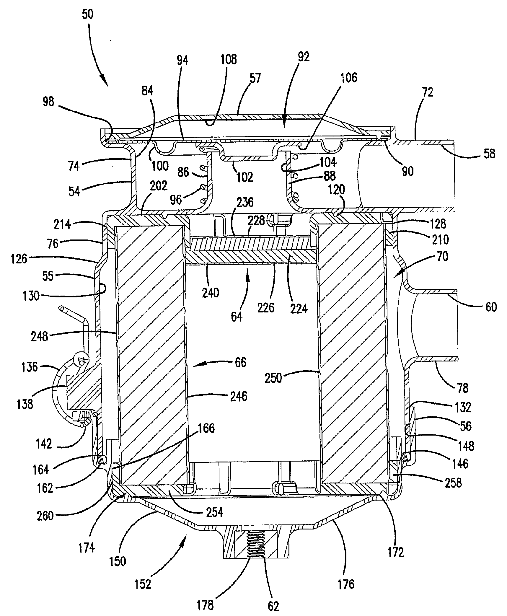
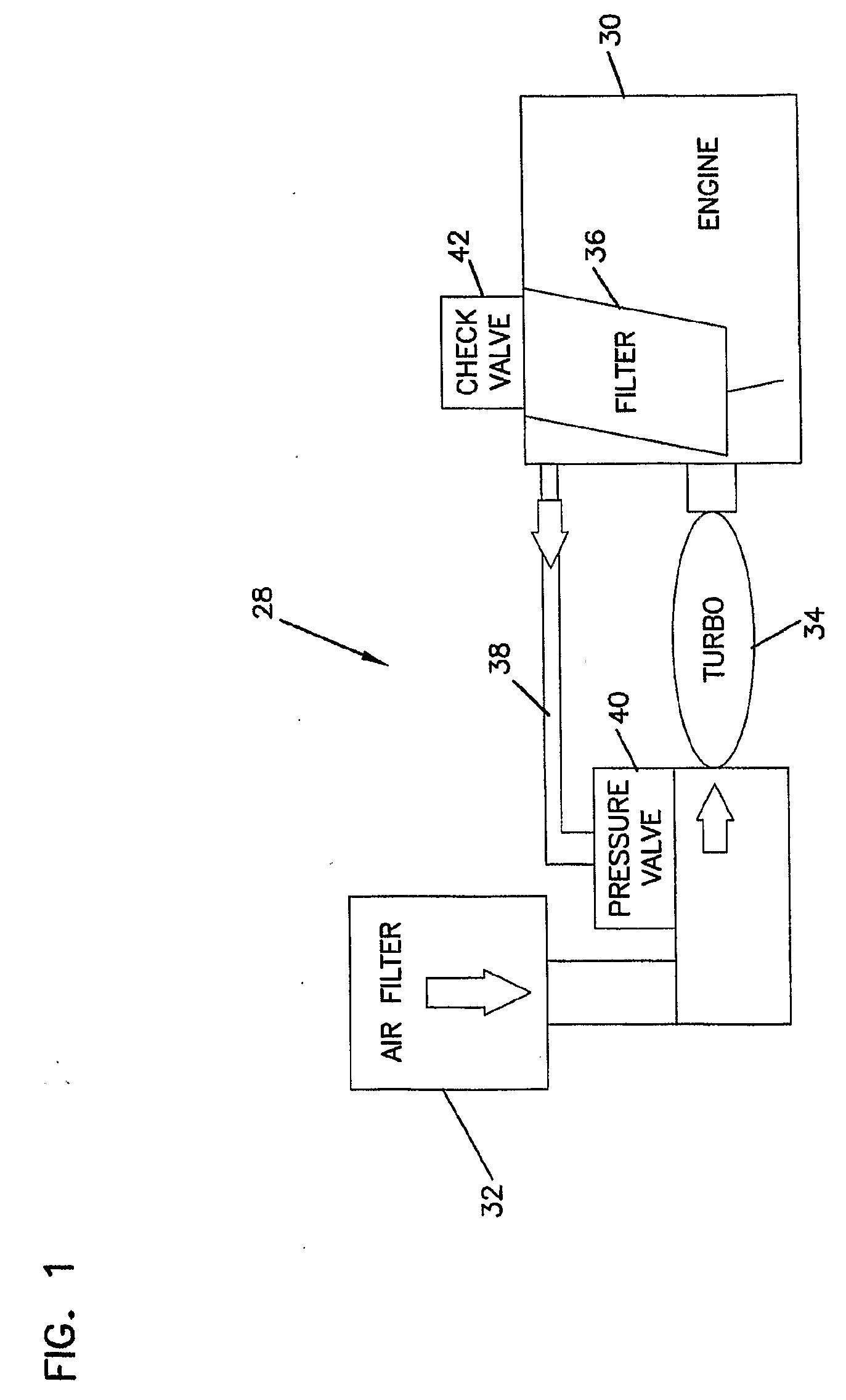
[0174]In operation, the depicted filter arrangement 400 works as follows. Blow-by gases from an engine crankcase are taken in through the gas flow inlet port 408. The gases pass into the interior 603 of the valve housing 424. The valve assembly 496 permits passage of the gas and into the gas flow aperture 490. From there, the gas passes through the first stage coalescer filter 416.

[0175]The gas flow passes through the upstream face 452, through the optional fibrous media 456, and out through the downstream face 454. The optional fibrous media 456 separates a portion of liquids from the rest of the gas stream. The collected liquids flow out of the media 456 and, in the depicted embodiment, either drips directly into the liquid flow outlet port 412, or drains along the wall 514 of the flow construction arrangement 510. After passing through the liquid flow outlet port 412, the liquid, which is often oil, may be directed back into the crankcase for reuse.

[0176]The gas stream...


PUM

PropertyMeasurementUnit
Lengthaaaaaaaaaa
Lengthaaaaaaaaaa
Lengthaaaaaaaaaa

Abstract

Crankcase ventilation arrangements are shown. Preferred wet laid media materials, for use in such arrangements are described. Also described and shown are example crankcase ventilation components, parts for use with a preferred media described and characterized.

Description

[0001]This application is being filed on 31 Jan. 2006, in the name of Donaldson Company, Inc., a U.S. national corporation, applicant for the designation of all countries except the US, and Robert M. Rogers, Brad Kalbaugh, Paul L. Kojetin, and Keh B. Dema, all citizens of the U.S., applicants for the designation of the US only, and claims priority to U.S. Provisional Application Ser. No. 60 / 650,051, filed Feb. 4, 2005.[0002]This application incorporates the following U.S. Patents herein by reference: U.S. Pat. No. 5,853,439; U.S. Pat. No. 6,171,355; U.S. Pat. No. 6,355,076; U.S. Pat. No. 6,143,049; U.S. Pat. No. 6,187,073; U.S. Pat. No. 6,290,739; U.S. Pat. No. 6,540,801; U.S. Pat. No. 6,530,969. This application incorporates by reference PCT Publication WO 01 / 47618 published on Jul. 5, 2001, and PCT Publication WO 00 / 32295 published on Jun. 8, 2000. This application incorporates by reference commonly assigned U.S. patent application Ser. No. 10 / 168,906 filed Jun. 20, 2002. This app...

Claims


Application Information

Patent Timeline
IPC IPC(8): F02M35/024B01D46/24
CPCB01D39/163B01D39/202Y10S55/19Y10T428/249962
Inventor ROGERS, ROBERTKAHLBAUGH, BRADKOJETIN, PAULDEMA, KEH
Owner DONALDSON CO INC
Why Eureka
Try Eureka