Cabinet having drawer anchoring device

Inactive Publication Date: 2008-10-09
HUANG SHUN LUNG
View PDF23 Cites 12 Cited by
  • Summary
  • Abstract
  • Description
  • Claims
  • Application Information

AI Technical Summary

Benefits of technology

[0012]The primary objective of the present invention is to provide a cabinet including an anchoring device for slidably and stably anchoring or coupling or securing a drawer to the cabinet and for preventing the drawer from being disengaged from the cabinet inadvertently.
[0013]In accordance with one aspect of the invention, there is provided a cabinet comprising a receptacle including two frames, one or more pairs of tracks attached to the frames respectively, the tracks each including a tubular member having a bore formed therein and having a groove formed in an inner portion of the track and formed by an inner side wall, and at least one drawer including an anchoring device extended from each of two sides of the drawer for slidably engaging with the tracks and for slidably attaching the drawer to the receptacle, the anchoring devices each including an upper flange extended outwardly from the sides of the drawer and slidably engaged through the groove and into the bore of the track, and an anchor member extended from the upper flange for slidably engaging with the inner side wall of the track and for limiting the anchoring devices of the drawer to slide relative to the tracks and for preventing the drawer from being disengaged from the receptacle inadvertently.

Problems solved by technology

However, for those cabinets made of wires or rods or beams or frames which may required be assembled or secured together with fasteners or the like, the wires or rods or beams or frames may have a good chance to be deformed or enlarged inadvertently such that the drawers will have a good chance to be disengaged from the cabinets inadvertently.

Method used


Image

  • Cabinet having drawer anchoring device
  • Cabinet having drawer anchoring device
  • Cabinet having drawer anchoring device

Examples


Embodiment Construction

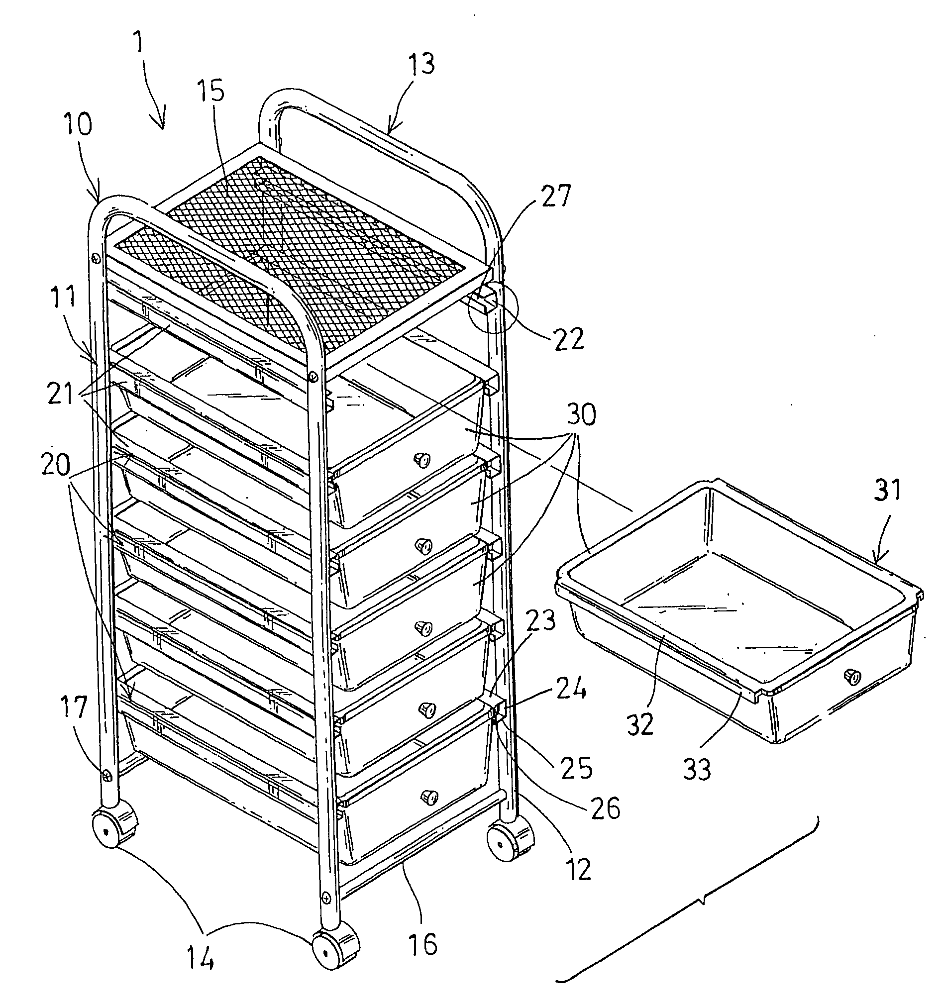
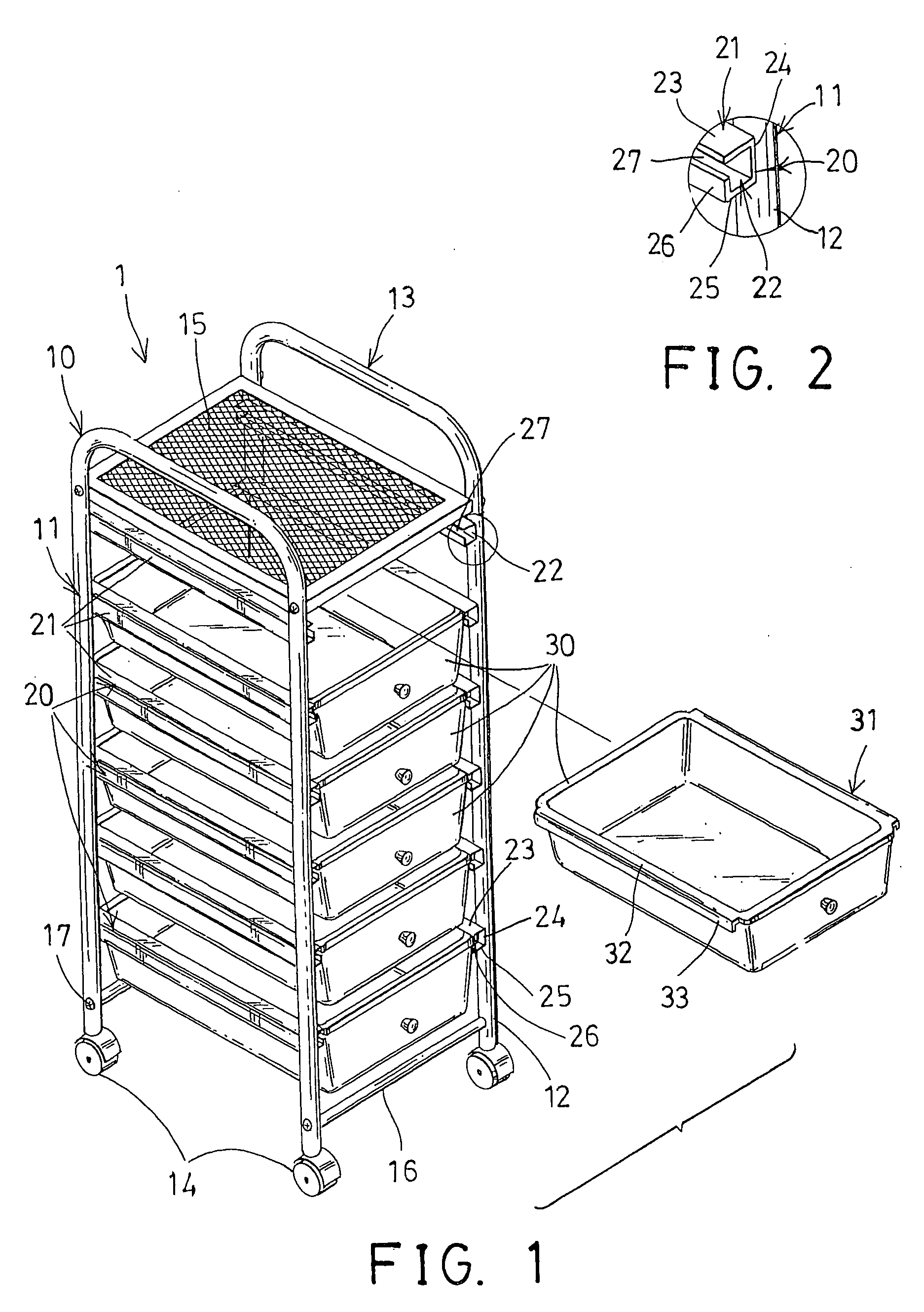
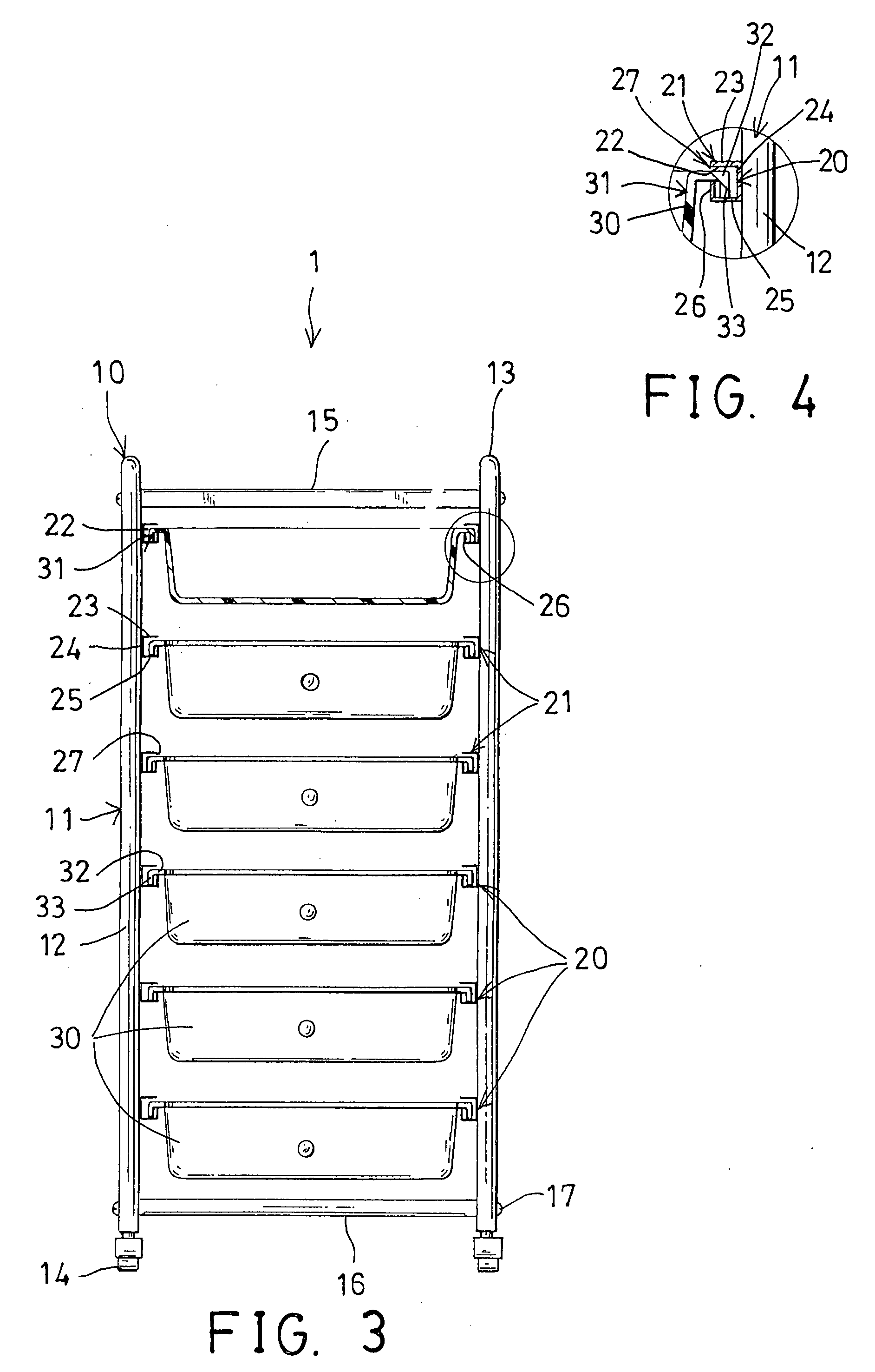
[0022]Referring to the drawings, and initially to FIGS. 1-3, a cabinet 1 in accordance with the present invention comprises a receptacle 10 including two inverted U-shaped frames 11 each having two posts 12 that are spaced away from each other and parallel to each other, and each having a handle 13 laterally coupled between the upper portions of the posts 12, and each having a wheel 14 attached to the bottom portion of each of the posts 12 for allowing the receptacle 10 to be easily moved elsewhere. The receptacle 10 further includes a net or a deck 15 laterally coupled between the upper portions of the frames 11, and one or more (such as two) rods 16 laterally coupled between the lower portions of the frames 11 for forming a spatial or three-dimensional structure for the receptacle 10. The posts 12 of the frames 11 and the deck 15 and / or the rods 16 may be secured together with such as latches or fasteners 17.

[0023]One or more pairs of track means or slide mechanisms or tracks 20 a...


PUM


Abstract

A cabinet includes a receptacle having two frames, and one or more pairs of tracks attached to the frames, the tracks each include a tubular member having a bore and a groove formed in an inner portion and formed by an inner side wall, and one or more drawers each include an anchoring device extended from each of two sides of the drawer for slidably engaging with the tracks and for slidably attaching the drawer to the receptacle, the anchoring devices each include an upper flange slidably engaged through the groove and into the bore of the track, and an anchor member extended from the upper flange for preventing the drawer from being disengaged from the receptacle inadvertently.

Description

BACKGROUND OF THE INVENTION[0001]1. Field of the Invention[0002]The present invention relates to a cabinet, and more particularly to a cabinet including an anchoring device for slidably anchoring or coupling or securing a drawer to the cabinet and for preventing the drawer from being disengaged from the cabinet inadvertently.[0003]2. Description of the Prior Art[0004]Typical cabinets or house buildings may comprise one or more drawers slidably anchored or coupled or secured to the cabinet or the walls of the house buildings.[0005]For example, U.S. Pat. No. 4,640,200 to Richardson discloses one of the typical transaction drawers slidably anchored or coupled or secured to the wall of the house buildings with one or more track means.[0006]The walls of the house buildings include a solid structure that will not be deformed or enlarged inadvertently such that the drawers will have no chance to be disengaged from the walls of the house buildings inadvertently, and such that the drawers ar...

Claims


Application Information

Patent Timeline
IPC IPC(8): A47B88/00
CPCA47B55/00A47B88/04A47B88/40
Inventor HUANG, SHUN LUNG
Owner HUANG SHUN LUNG
Why Eureka
Try Eureka