
Bracket equipped with a paper releaser mechanism

Inactive Publication Date: 2007-01-16
SHARP KK
View PDF4 Cites 2 Cited by
  • Summary
  • Abstract
  • Description
  • Claims
  • Application Information

AI Technical Summary

Benefits of technology

[0008]An object of the present invention is to provide a bracket equipped with a paper release mechanism which has a simple structure and thus saves assembly time, and a document reading apparatus employing such a bracket.
[0010]In this structure, the release lever for releasing the back roller and the close-contact-type image sensor from a state in which they are pressed against each other is formed integrally with the bracket. This makes it possible to remove a jammed document easily in a simple structure without requiring extra parts.
[0012]In this structure, when the release lever is operated, the projection formed on the bracket makes contact with the close-contact-type image sensor and detaches it from the back roller. The projection is formed integrally with the bracket. This helps simplify the structure without requiring extra parts.
[0014]In this structure, the disengagement-preventing portion that is guided along the disengagement-preventing guide portion formed in the cabinet is formed integrally with the bracket. This helps prevent the bracket from disengaging from the cabinet.

Problems solved by technology

H8-65446) requires extra parts, namely the release levers fitted on the shaft of the back roller, and thus has disadvantages of increasing the number of parts, complicating the structure, increasing assembly time, and the like.

Method used


Image

  • Bracket equipped with a paper releaser mechanism
  • Bracket equipped with a paper releaser mechanism
  • Bracket equipped with a paper releaser mechanism

Examples


Embodiment Construction

[0020]Hereinafter, a bracket equipped with a paper release mechanism according to the invention will be described with reference to the drawings.

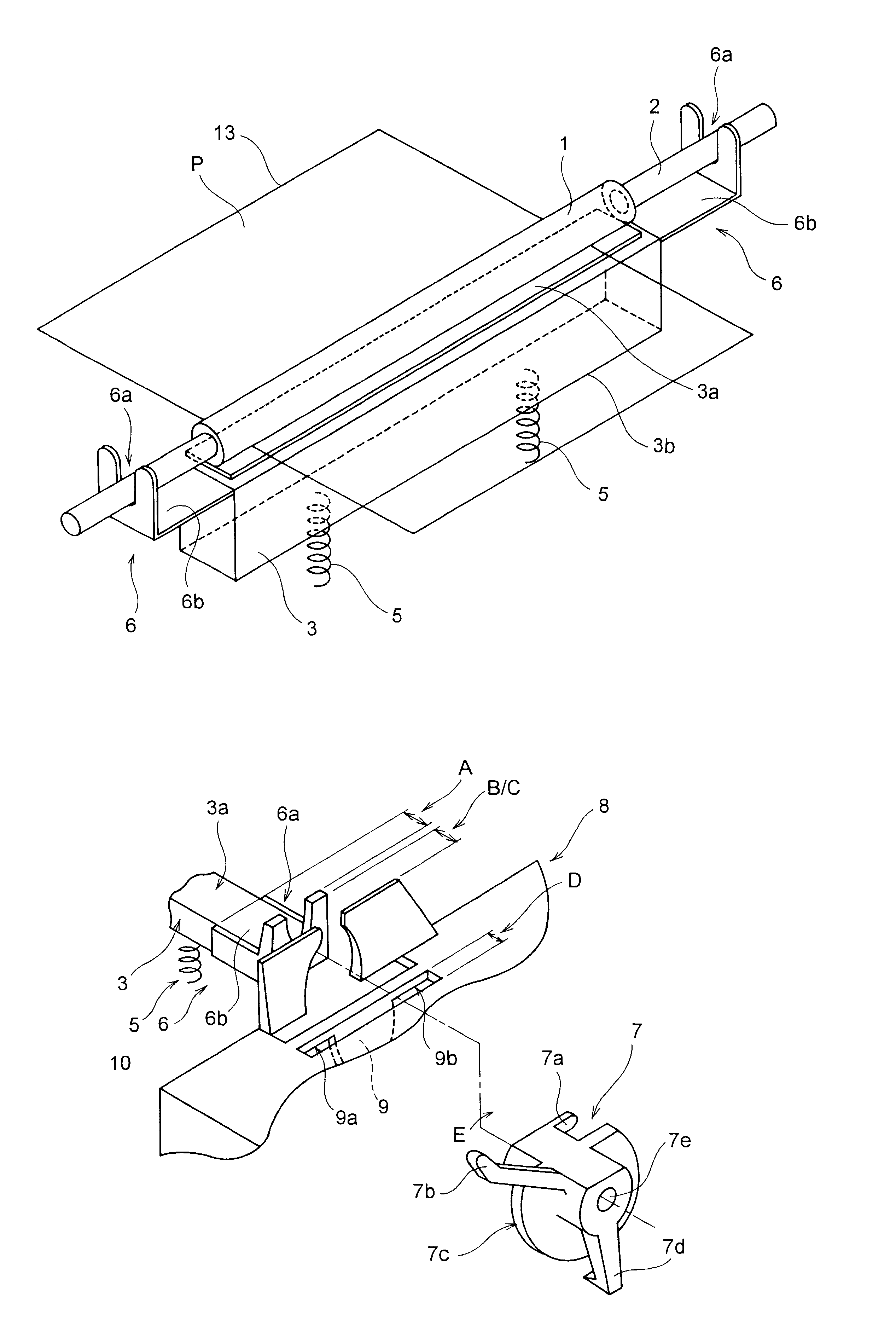
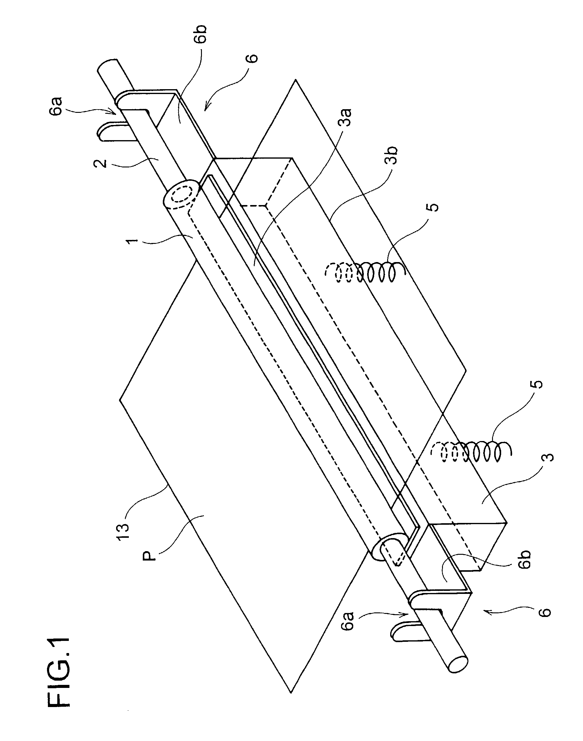
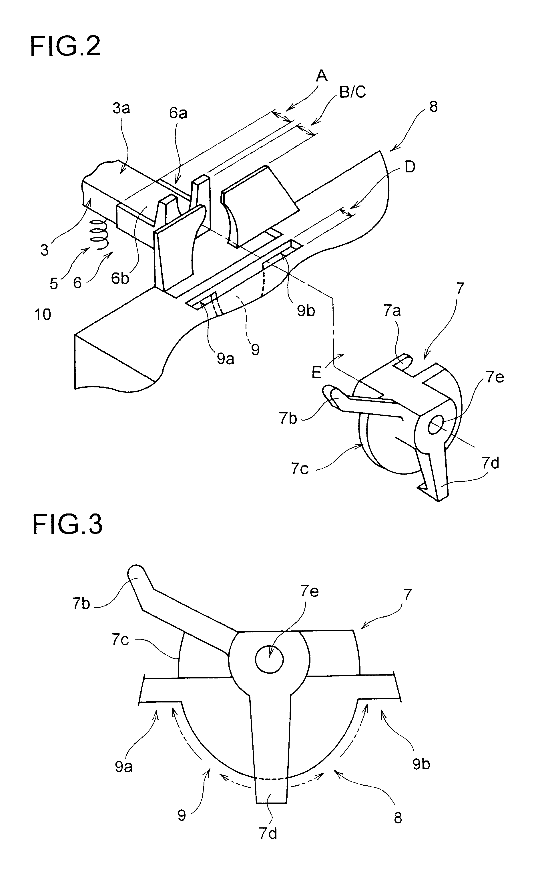
[0021]FIG. 1 shows the basic structure of the document reader portion of a facsimile machine or the like, and FIG. 2 shows how the bracket equipped with a paper release mechanism is fitted. In these figures, reference numeral 1 represents a back roller made of rubber for feeding and thereby transporting a document P, reference numeral 2 represents a shaft provided along the axis of the back roller 1, and reference numeral 3 represents a close-contact-type image sensor (CIS) shaped like a box and supported elastically against the back roller 1, with reference numerals 3a and 3b respectively representing a reading portion and a bottom portion thereof. The bottom portion 3b of the close-contact-type image sensor 3 is, in two places, elastically supported by springs 5 so that the reading portion 3a thereof is kept pressed against the peripheral...


PUM


Abstract

A bracket that rotatably supports a shaft provided along the axis of a back roller for feeding and thereby transporting a document pinched between the back roller and a close-contact-type image sensor elastically supported on a cabinet and that is fitted to the cabinet so as to be rotatable about the shaft is formed integrally with a release lever for releasing the back roller and the close-contact-type image sensor from a state in which they are pressed against each other.

Description

BACKGROUND OF THE INVENTION[0001]1. Field of the Invention[0002]The present invention relates to a bracket equipped with a paper releaser mechanism for use in the document reader portion of a facsimile machine or the like, and to a document reading apparatus employing such a bracket.[0003]2. Description of the Prior Art[0004]In a facsimile machine or the like that employs a close-contact-type image sensor as a document reading means, the document reader portion thereof is, for example as disclosed in Japanese Patent Application Laid-Open No. H8-65446, structured as follows. In the path through which a document P is transported, a back roller and an image sensor portion pressed against it with a spring are provided, so that the image on the document fed in by the back roller is read continuously while the image is kept pressed against the reading surface of the image sensor.[0005]In a document reader portion that employs a pressure-contact-type image sensor like this, when a document...

Claims


Application Information

Patent Timeline
IPC IPC(8): H04N1/04H04N1/40B65H29/20H04N1/00
CPCH04N1/0057
Inventor FUJII, MAMORUSHIRAISHI, KENICHIMIYAKE, HIDEYUKI
Owner SHARP KK
Learn More