Surgical visual feedback and eye fixation method and apparatus

a visual feedback and eye fixation technology, applied in the field of eye fixation, can solve the problems of not providing the best alignment of the eye and the laser beam, not providing visual feedback for the operator, and the axis of astigmatism of the patient's eye is also likely to be misaligned, so as to facilitate the alignment of an instrumen

Inactive Publication Date: 2008-10-09
VAN SAARLOOS PAUL PHILLIP +1
View PDF4 Cites 4 Cited by
  • Summary
  • Abstract
  • Description
  • Claims
  • Application Information

AI Technical Summary

Problems solved by technology

However, this arrangement does not necessarily provide the best alignment of the eye and the laser beam, nor does it provide visual feedback for the operator concerning the status of the eye or the laser.
The axis of astigmatism of the patient's eye is also likely to be misaligned when the patent is supine and fixating on a point of light.
Focussing on a point of light (the flashing LED), instead of the linear horizon, does not provide a proper point of horizontal or vertical reference.
The globe is therefore liable to rotate fractionally, possibly resulting in misalignment of the treatment of the eye's axis of astigmatism.
This method of determining the axis of astigmatism and aligning the surgical laser is not ideal.

Method used


Image

  • Surgical visual feedback and eye fixation method and apparatus
  • Surgical visual feedback and eye fixation method and apparatus
  • Surgical visual feedback and eye fixation method and apparatus

Examples


Embodiment Construction

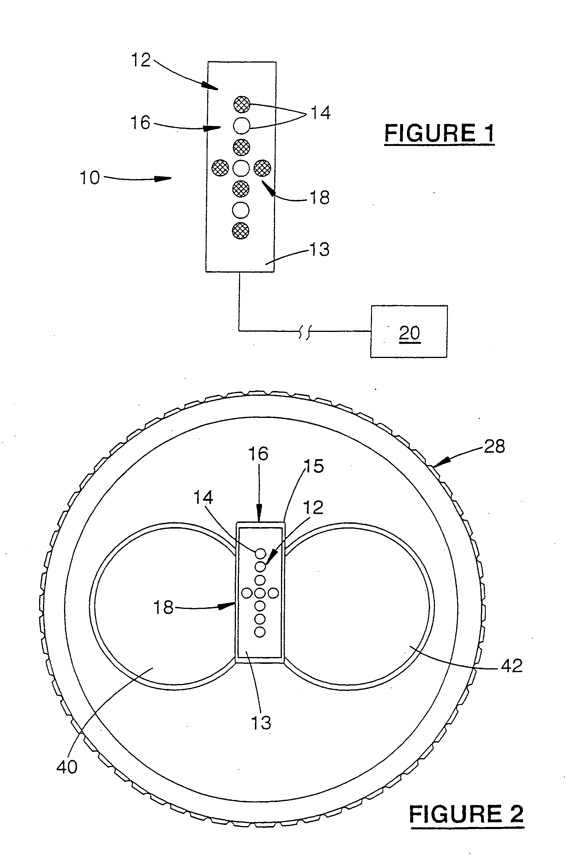
[0056]Referring to FIGS. 1 and 2, there is presented a schematic view of a patient's eye fixation apparatus 10 according to a preferred embodiment of the present invention. The apparatus 10 includes a fixation target in the form of a cross 12 formed by surface mounted light emitting diodes, LEDs 14, arranged in two linear arrays to define intersecting elongate components or axes 16, 18 perpendicular to one another. The LEDs are fixed to a printed circuit board (PCB) 13, in turn arranged on an elongate lipped substrate 15. Substrate 15 is positioned on the front of the surgical microscope 28, symmetrically between the adjacent stereo oculars 40,42, so as to be clearly observable by the patient. Alternatively, cross 12 may be located elsewhere within the surgical laser, and projected to optically appear as if it is placed between the oculars of the microscope.

[0057]Substrate 15 is fixed in position on the microscope so that cross 12 has a fixed orientation. “Vertical” axis 16 of the c...


PUM


Abstract

A fixation apparatus is provided that limits rotation of the ocular globe of an eye, to facilitate alignment of an instrument with the axis of astigmatism of the eye. The apparatus includes fixation target means (12) for locating in the field of view of the eye so that the eye may fixate on the target. The fixation target means includes or consists of at least one elongate component (16). Also disclosed is a corresponding method, and method and apparatus for supplying visual feedback to an operator during refractive surgery of an eye of a patient.

Description

FIELD OF THE INVENTION[0001]The present invention relates, in different aspects, to eye fixation and to the provision of visual feedback to a surgeon, during the delivery of medical laser procedures, particularly in the fields of ophthalmic surgical procedures, such as Photorefractive Keratectomy (PRK) and Laser-in-situ Keratomileusis (LASIK), or any laser based refractive correction. The invention will be described with reference to these applications, though it is to be understood that other applications are envisaged.BACKGROUND ART[0002]Most existing refractive laser delivery systems provide little feedback for the operator (typically a surgeon). Usually a crosshair graticule is superimposed through the microscope optics to help the operator aim the laser beam correctly onto the cornea. A fixation target or light, such as a flashing LED, is used to ensure that the patient's eye remains correctly aligned during the surgery. However, this arrangement does not necessarily provide th...

Claims


Application Information

Patent Timeline
Patent Type & Authority Applications(United States)
IPC IPC(8): A61F9/008A61B18/20A61F9/01A61F9/013
CPCA61F9/008A61F9/00804A61F9/013A61F2009/00872A61F2009/00882
Inventor VAN SAARLOOS, PAUL PHILLIPDISHLER, JON
Owner VAN SAARLOOS PAUL PHILLIP
Why Eureka
Try Eureka