
Ophthalmic apparatus

a technology of ophthalmology and ophthalmology, applied in the field of ophthalmology equipment, can solve the problems of patient inability to confirm a manner of view after correction, difficult to see, and not simply proper to perform correction

Inactive Publication Date: 2007-10-16
NIDEK CO LTD
View PDF6 Cites 5 Cited by
  • Summary
  • Abstract
  • Description
  • Claims
  • Application Information

AI Technical Summary

Benefits of technology

The invention is an ophthalmic apparatus that can help patients see after surgery and get information needed for refractive surgery. It has a target presenting optical system, an aberration correcting optical system, an input unit for inputting data to correct the patient's eye, and a control unit to control the aberration correcting optical system based on the inputted data. The technical effect of the invention is to improve the accuracy of refractive surgery and provide better visual outcomes for patients.

Problems solved by technology

However, in the refractive correction by changing the corneal shape, different from the refractive correction with the spectacles or contact lenses, a patient cannot confirm a manner of view after correction until posterior to surgery.
Further, since the manner of view after surgery (after correction) which the patient prefers is different according to his / her own circumstances (a lifestyle, a working environment, and the like), it is not simply proper to perform correction such that an object forms an image at one point on a retina.
For example, in a case where an accommodation function of the eye is lowered due to presbyopia, if correction is made such that an object at a long (far) distance forms an image at one point on the retina while eliminating the higher order aberration, there may be cases where an object at a short (near) distance becomes difficult to see and visual acuity at a distance in daily needs is insufficiently obtained.

Method used


Image

  • Ophthalmic apparatus
  • Ophthalmic apparatus
  • Ophthalmic apparatus

Examples


Embodiment Construction

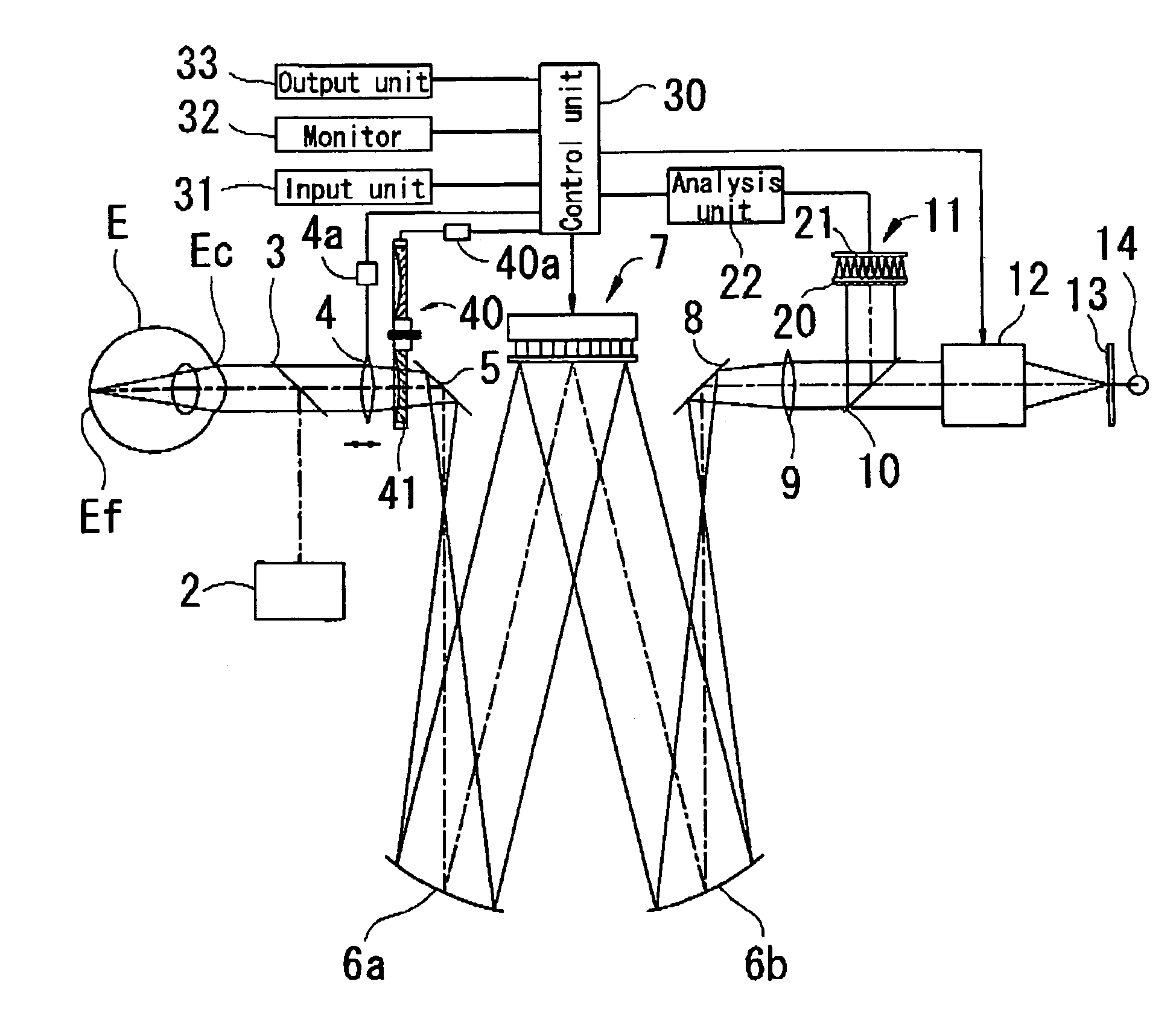
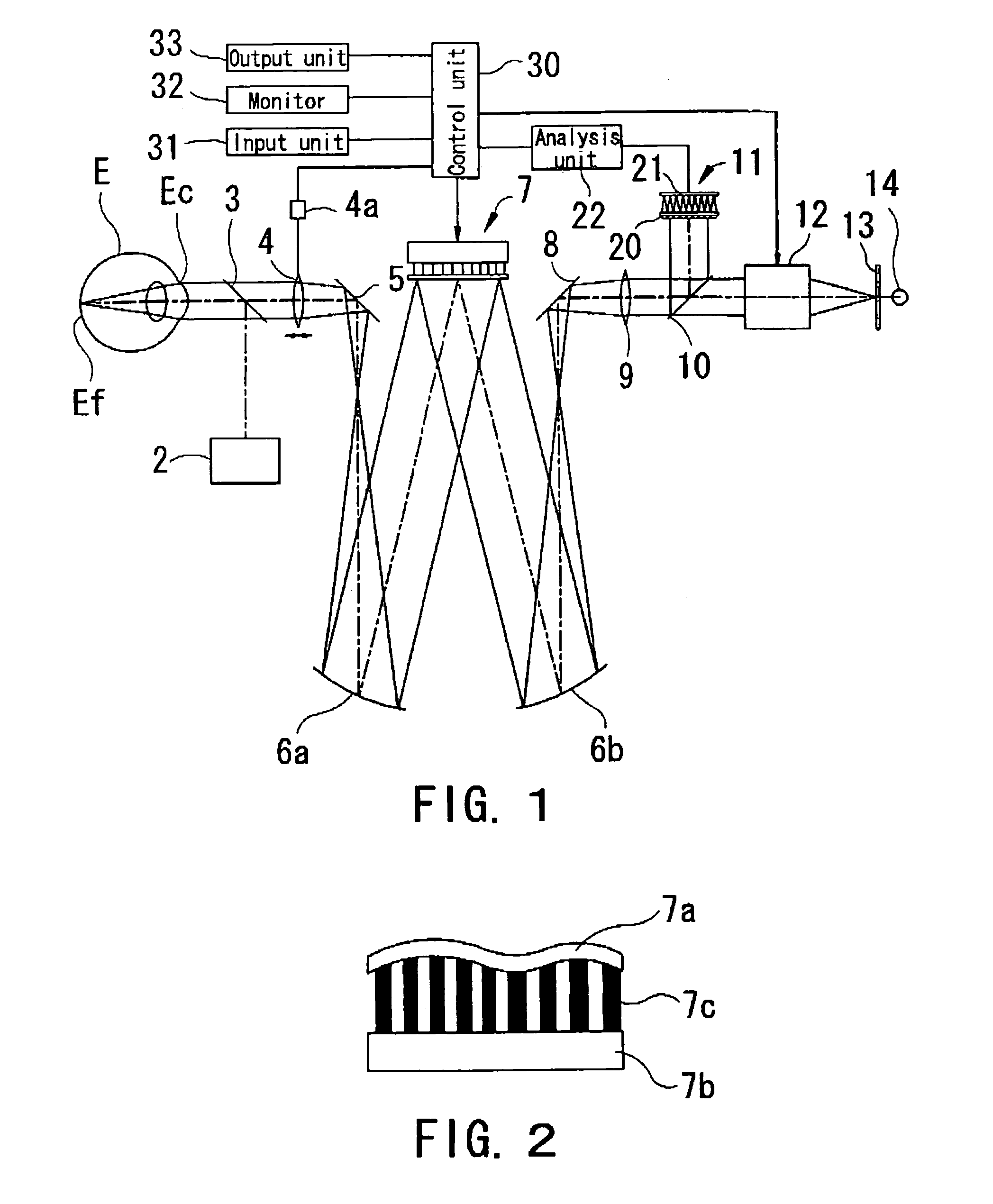
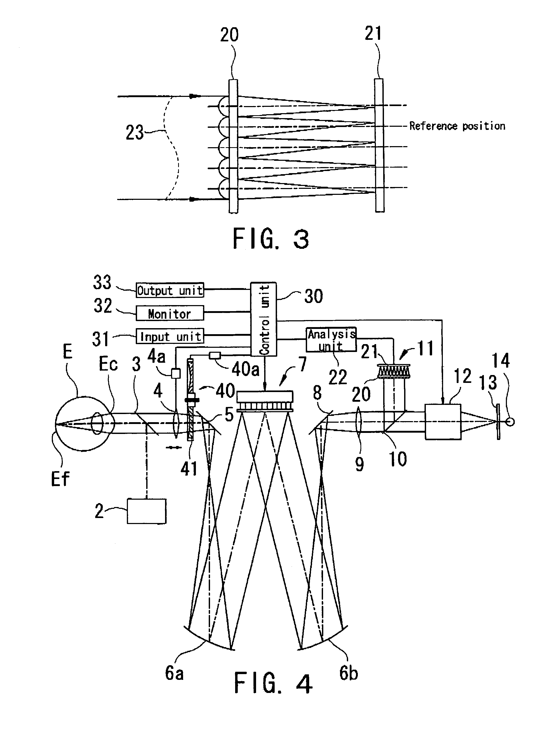
[0015]A detailed description of one preferred embodiment of an ophthalmic apparatus embodied by the present invention is provided below with reference to the accompanying drawings. FIG. 1 is a view showing a schematic configuration of an optical system in an ophthalmic apparatus consistent with the present invention. The optical system is broadly divided into an aberration measuring optical system, an aberration correcting optical system, and a target presenting optical system.

[0016]First, the aberration measuring optical system and the aberration correcting optical system are described. A light source 2, which is constituted of an SLD (Super Luminescent Diode), an LD (Laser Diode), or the like, emits a thin beam of infrared light. An infrared half mirror 3, having properties of reflecting a part of infrared light and transmitting a part thereof as well as transmitting nearly a whole part of visible light, reflects a part of the infrared light emitted from the light source 2 toward ...


PUM


Abstract

An ophthalmic apparatus which allows a patient to experience a manner of view after surgery (after correction) prior to surgery (prior to correction) and is capable of obtaining information required for performing refractive surgery suitable for the patient. The apparatus, which allows a patient to experience a manner of view after correction of optical aberration of a patient's eye, includes a target presenting optical system for presenting a target which the patient's eye is made to visually recognize, an aberration correcting optical system, which is arranged within an optical path of the target presenting optical system and has a light shaping optical unit which performs light shaping, for correcting the optical aberration of the patient's eye, an input unit which inputs data for correcting the optical aberration of the patient's eye, and a control unit which controls driving of the aberration correcting optical system based on the inputted correction data.

Description

BACKGROUND OF THE INVENTION[0001]1. Field of the Invention[0002]The present invention relates to an ophthalmic apparatus which allows a patient to experience a manner of view after surgery (after correction) prior to refractive surgery to change a corneal shape.[0003]2. Description of Related Art[0004]Conventionally, when ametropia (refractive error) of an eye is corrected, spectacles or contact lenses have been used. For the same purpose, recently, refractive surgery is increasingly performed for ablating a cornea with a laser beam to change a corneal shape. In most recent times, a method is proposed where wavefront aberration of an eyeball is measured and an ablation amount is determined based on a result of the measurement so as to correct even higher order aberration of an optical system of the eyeball by ablating the cornea based on the determined ablation amount.[0005]However, in the refractive correction by changing the corneal shape, different from the refractive correction ...

Claims


Application Information

Patent Timeline
Patent Type & Authority Patents(United States)
IPC IPC(8): A61B3/10A61B3/103G01J9/00
CPCG01J9/00A61B3/1015
Inventor SUMIYA, TOSHIFUMI
Owner NIDEK CO LTD
Learn More