Method and device for handling elongate strength members

a technology of strength members and elongated parts, applied in the field of strength members, can solve the problems of cable twisting or coiling in one direction, durkee et al. methodology would not be applicable to cable, and composite cable with parallel composite rods

Active Publication Date: 2008-10-16
AIRLOG ACQUISITION CORP
View PDF21 Cites 28 Cited by
  • Summary
  • Abstract
  • Description
  • Claims
  • Application Information

AI Technical Summary

Benefits of technology

[0007]The invention provides a device, method and a coiled form of a strength member wherein the individual composite rods, or metal wires, or plastic fibers in the strength member are bundled together in a generally parallel, untwisted and unspiraled orientation when the strength member follows along a generally straight path, but when the strength member is coiled, e.g., on a spool device, the strength member will be twisted along it longitudinal axis and the individual composite rods, or metal wires, or plastic fibers forming the strength member will be in a twisted and spiraled orientation so that no undue stresses will be exerted on the coiled strength member. As noted above, this twisting and spiraling will be more pronounced for composite rods, or metal wires or plastic fibers lying closer to the outer perimeter of the strength member and composite rods, or metal wires or plastic fibers lying closer to the centerline of the strength member will be less twisted and spiraled or possible not twisted or spiraled.

Problems solved by technology

Failure to deal with the natural case may result in cables that have a tendency to twist or coil in one direction or the other.
Furthermore, the Durkee et al. methodology would not be applicable to cables in which the individual wires and strands are not allowed to bow out, such as cables constructed with inflexible binding and / or overwrapping material.
In contrast, composite cables with parallel composite rods, such as those disclosed in U.S. Pat. No. 7,137,617, are more difficult to handle and wind on a spool and the like.
The machinery used to form very long lengths of larger diameter cables can be quite large and expensive due to the necessity of twisting together a number of very long rods, which rods themselves are spooled out from large spools, which number of large spools are themselves on a rotating carriage.
While stranded cables, whether formed of metal wire, plastics rods or fibers, or composite rods, can be more easily handled, there are some disadvantages with stranded cables.
In the case of applications where such cables may sway, swing, or otherwise move, for example, as in mooring cables where they can be moved by ocean currents and the like, the effects of internal rubbing and abrasion of the composite rods, metal wires or plastic fibers in the crossover areas, for example, can weaken the cable.
Moreover, in particular case of stranded composite cables, that are made of composite rods which are generally less stretchable than other materials, because of different rod lengths, some rods may carry more tension than other rods and this can result in less than optimal cable strength or failure of the cable.

Method used


Image

  • Method and device for handling elongate strength members
  • Method and device for handling elongate strength members
  • Method and device for handling elongate strength members

Examples


Embodiment Construction

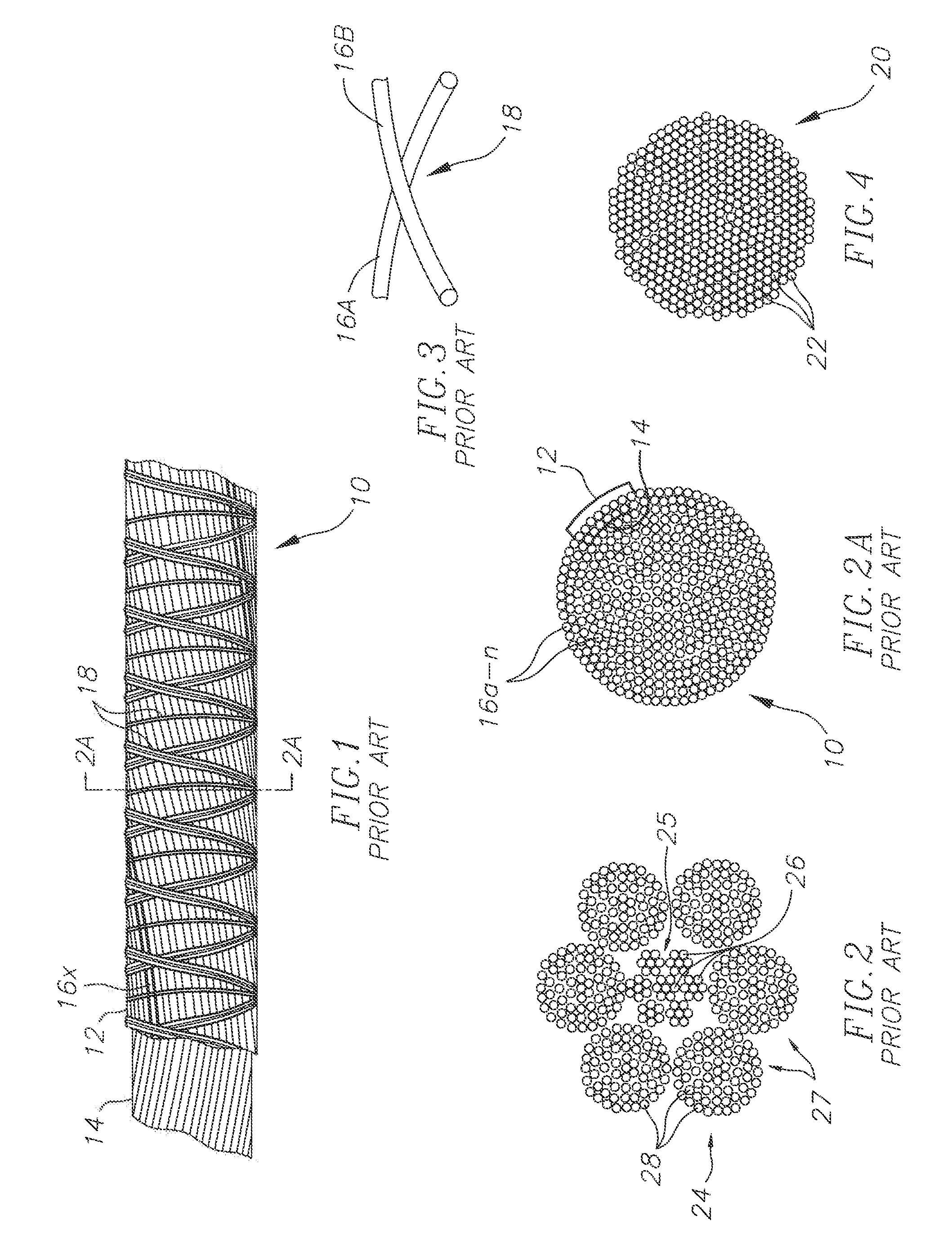
[0034]FIG. 1 is a top, partially exposed view of a section of a prior art stranded cable 10 showing two counter-helically wound layers 12 and 14 of composite rods 16a-n, wherein n=any number of rods used to make up the cable 10. Also shown are binding threads 18 which are wrapped around the composite rods, or metal wires, or plastic fibers, etc. to hold them together Other than the binding thread, and a cover material, such as a plastic layer (not shown), the composite rods, or metal wires, or plastic fibers are otherwise not held together and the composite rods, or metal wires, or plastic fibers 16a-n are capable of moving laterally with respect to each other, such as when the cable 10 is bent or curved, or such as when it is coiled around a spool. One rod, or metal wire, or plastic fiber 16x is shown with contrasting shading to show how the composite rods, or metal wires, or plastic fibers are counter-helically spiraled to make up the stranded cable 10.

[0035]FIG. 2 is a cross-sect...


PUM

PropertyMeasurementUnit
diameteraaaaaaaaaa
diameteraaaaaaaaaa
diameteraaaaaaaaaa

Abstract

A method and device for handling an elongate strength member. In the method, an elongate strength member with a plurality of elongate composite rods, or metal wires or plastic fibers are bundled together with the composite rods, or metal wires, or plastic fibers in a generally parallel and untwisted and un-spiraled arrangement when the elongate strength member is extended along a generally straight path, wherein the composite rods are longitudinally and rotatably moveable relative to each other. It is then twisted relative to a longitudinal dimension of the elongate strength member and the path of the elongate strength member is curved, such as by coiling.

Description

BACKGROUND[0001]This invention relates to the field of strength members and how to handle them, and more particularly to a device, method and coiled form of a strength member wherein the individual composite rods, or metal wires, or plastic fibers, or other materials in the strength member are bundled together in a generally parallel, untwisted and unspiraled orientation when the strength member follows along a generally straight path, but when the strength member is coiled, e.g., on a spool device, the strength member will be twisted along it longitudinal axis and the individual composite rods, or metal wires or plastic fibers forming the strength member will be in a twisted and spiraled orientation so that no undue stresses will be exerted on the coiled strength member. This twisting and spiraling will be more pronounced for rods, or wires, or fibers lying closer to the outer perimeter of the strength member and rods, or metal wires, or plastic fibers lying closer to a centerline ...

Claims


Application Information

Patent Timeline
Patent Type & Authority Applications(United States)
IPC IPC(8): B23P19/00
CPCB21F7/00D07B2201/1012D07B2201/1092D07B2201/2009D07B2201/2033D07B2205/3007Y10T29/49801Y10T29/49863Y10T29/49874Y10T29/5353Y10T428/2931D07B2801/10
Inventor BUCKLEY, DAVID L.
Owner AIRLOG ACQUISITION CORP
Why Eureka
Try Eureka