Pneumatic Tire

a technology of pneumatic tires and pneumatic discs, applied in the field of pneumatic tires, can solve the problems of affecting steering stability, affecting the rigidity of blockages, and affecting the stability of steering, and achieve the effect of improving snow performan

Inactive Publication Date: 2008-10-23
BRIDGESTONE CORP
View PDF1 Cites 6 Cited by
  • Summary
  • Abstract
  • Description
  • Claims
  • Application Information

AI Technical Summary

Benefits of technology

[0024]Because the present invention has the above-described configuration, it can realize a pneumatic tire whose snow performance is improved without causing steering stability when traveling on a dry road surface to drop that much.

Problems solved by technology

For this reason, the ground contact pressure in the vicinity of the grooves drops, which affects the steering stability when traveling on a dry road surface (dry performance, hereinafter), and noise during travel becomes large because it becomes easier for block vibration to occur.
However, when a measure noted above is performed, the block rigidity may decline and new problems might occur.
Even when a measure to add sipes is performed, the block rigidity may decline.

Method used


Image

  • Pneumatic Tire
  • Pneumatic Tire
  • Pneumatic Tire

Examples


experimental example

[0041]In the present experimental example, an experiment was performed to evaluate dry performance and snow performance within a period of time when traveling speed was 10 km / h to 45 km / h using a European front-engine rear-drive car. In the present experimental example, the tire size was 225 / 50R17. Further, the rim width was 17×7.5, and the internal pressure was 240 kPa at the front side and 270 kPa at the rear side. The experimental conditions and evaluation results described in detail below are shown in Table 1.

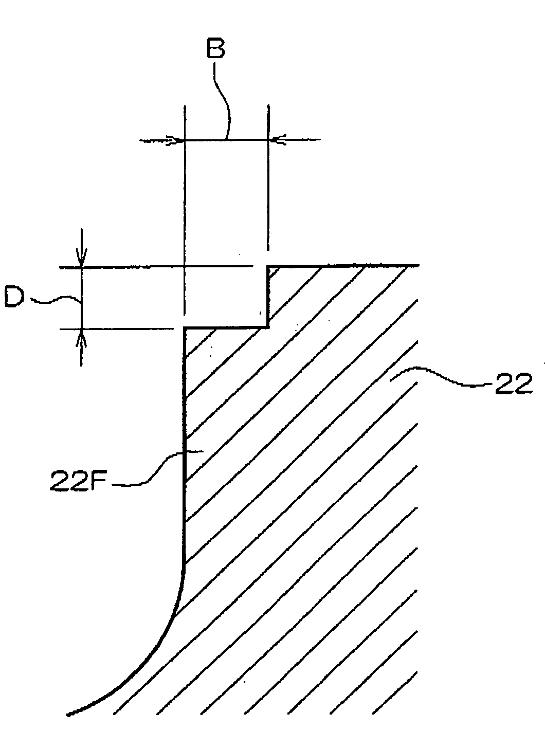
TABLE 1Compara-Compara-Conven-tivetivetionalExampleExample 1Example 2ExampleStepLength1.50.82.5NonePortions(mm)Depth (mm)2.05.02.5NoneDry Performance7.06.56.07.0Snow Performance125105120100

[0042]In the present experimental example, first, dry performance and snow performance were examined when a conventional pneumatic tire was attached to a vehicle. The evaluation of dry performance was performed on BSPG and the evaluation of snow performance was performed on HPG (see Conve...


PUM


Abstract

[Subject] To provide a pneumatic tire whose snow performance is improved without affecting its dry performance.
[Measures for Addressing the Subject] Step portions 22F and 22R that are continuous so as to protrude respectively from step-in sides and kick-out sides of each of blocks 20 configuring a tread portion 16 are disposed in a pneumatic tire, and the step portions 22 are disposed in a staggered manner in the tread portion 16. Thus, even when the step portions 22 are disposed, the rigidity of the blocks 20 does not decline that much and dry performance is not affected that much. Further, snow performance can be improved by the edge pressure of the step portions 22.

Description

TECHNICAL FIELD[0001]The present invention relates to a pneumatic tire including blocks in a tread portion.BACKGROUND ART[0002]Conventionally, forming steps in blocks configuring a tread portion in order to improve tire traveling performance has been proposed (e.g., see Japanese Patent Application Laid-Open (JP-A) No. 63-176704, JP-A No 3-186406 and JP-A No. 4-278809).[0003]For example, in order to improve traction performance on snow (snow performance, hereinafter), main grooves in the tire circumferential direction are disposed in the tread portion and lug grooves leading from the outermost main groove to the ground contact end are disposed. The lug grooves formed in this manner cause shear force by forming snow columns inside the grooves when they bite into a snow surface, and further cause traction force on snow in combination with an edge effect (wedge effect).[0004]Incidentally, when such lug grooves are formed in the tread portion, the rigidity of the tread portion declines. ...

Claims


Application Information

Patent Timeline
Patent Type & Authority Applications(United States)
IPC IPC(8): B60C11/03
CPCB60C11/0302B60C11/12B60C11/13B60C2011/1213
Inventor KUSANO, AKIO
Owner BRIDGESTONE CORP
Why Eureka
Try Eureka