Dust collecting apparatus for vacuum cleaner

a technology for vacuum cleaners and dust collecting equipment, which is applied in the direction of filtration separation, cleaning filter means, and separation processes, etc., can solve the problems of reducing the suction force of pulling in dirt from the surface to be cleaned, increasing the pressure inside the dust collecting apparatus, and inconvenience for users, so as to increase the amount of dust collected

Inactive Publication Date: 2008-10-30
SAMSUNG GWANGJU ELECTRONICS CO LTD
View PDF36 Cites 73 Cited by
  • Summary
  • Abstract
  • Description
  • Claims
  • Application Information

AI Technical Summary

Benefits of technology

[0011]An aspect of the present disclosure is to address at least the above problems and/or disadvantages and to provide at least the advantages described below. Accordingly, an aspect of the present disclosure is to provide a ...

Problems solved by technology

In this situation, if the dust collecting apparatus has a small size, a user may experience inconvenience due to the frequency with which the dust collecting apparatus needs to be emptied.
Additi...

Method used


Image

  • Dust collecting apparatus for vacuum cleaner
  • Dust collecting apparatus for vacuum cleaner
  • Dust collecting apparatus for vacuum cleaner

Examples


Embodiment Construction

[0021]Hereinafter, a dust-collecting apparatus of a vacuum cleaner according to exemplary embodiments of the present disclosure will be described in detail with reference to the accompanying drawings.

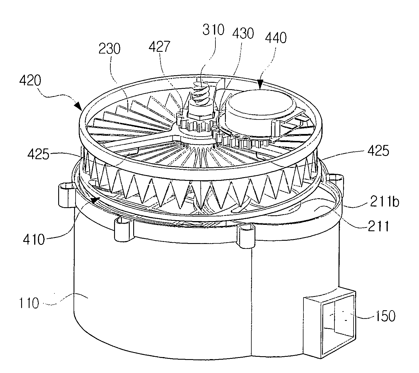
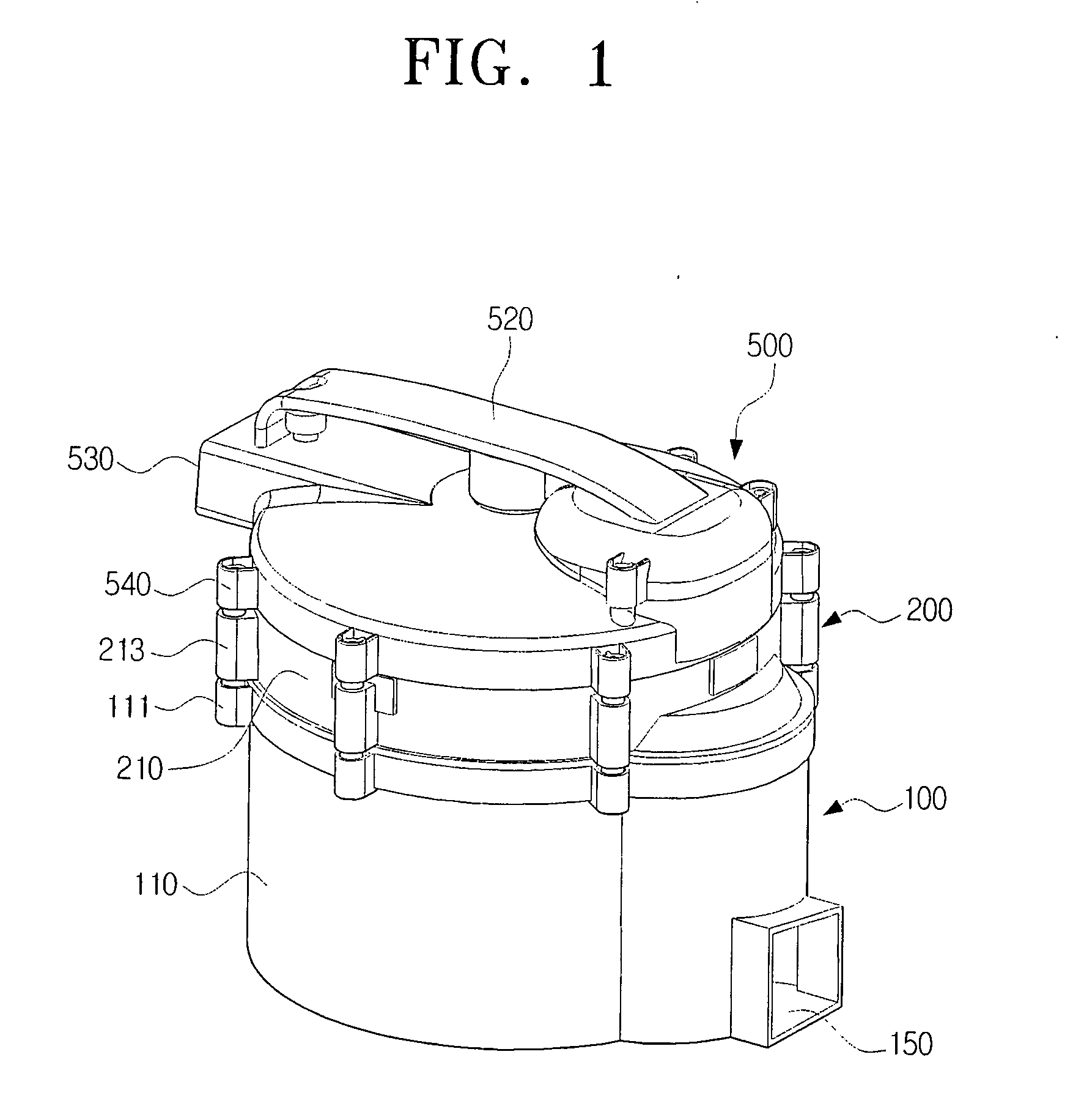
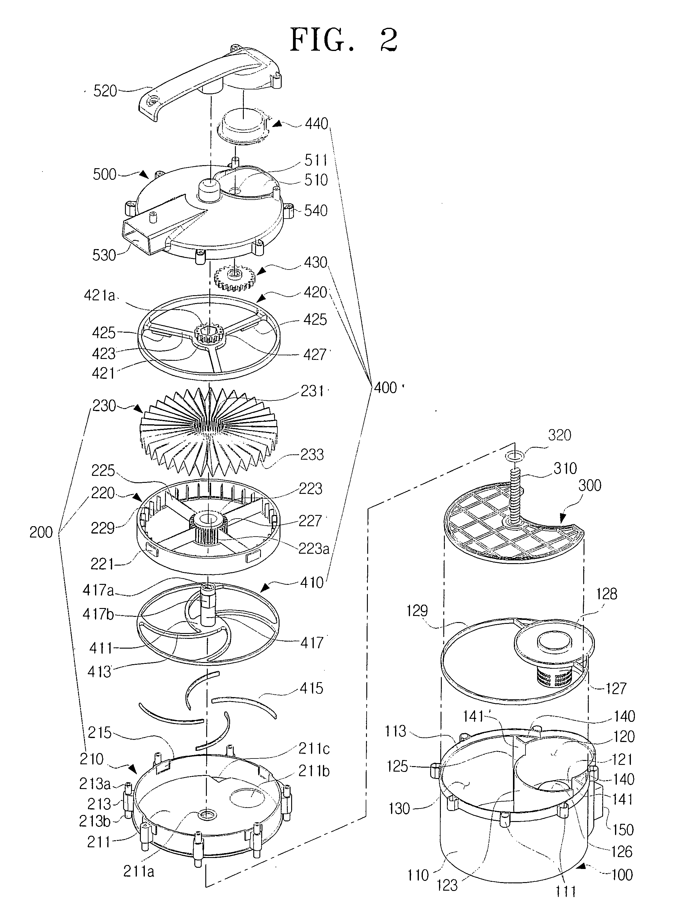
[0022]Referring to FIG. 1, a dust collecting apparatus according to an exemplary embodiment of the present disclosure comprises a dust collecting unit 100, a filter unit 200, a dust compression plate 300, a rotating unit 400 and a top cover 500. Hereinafter, the elements 100, 200, 300, 400 and 500 will be described in detail with reference to FIGS. 2 and 3.

[0023]The dust collecting unit 100 comprises a dust collecting case 110, and a cyclone chamber 120, a dust collecting chamber 130 and a fine dust collecting chamber 140 which are spaced apart from each other within the dust collecting case 110. Additionally, the dust collecting unit 100 comprises an inlet 150 which fluidly communicates with the cyclone chamber 120.

[0024]The dust collecting case 110 has a substantially cylindrical shap...


PUM

PropertyMeasurementUnit
Thicknessaaaaaaaaaa

Abstract

A dust collecting apparatus for a vacuum cleaner is provided. The dust collecting apparatus includes a dust collecting unit detachably mounted in a main body of the vacuum cleaner, to separate and collect dust from drawn-in air flowing therein; a filter unit disposed above the dust collecting unit, the filter unit comprising a filter to filter fine dust particles contained in air from which the dust has been separated by the dust collecting unit; a top cover to cover the filter unit and to discharge the air filtered through the filter; a rotating unit, which is disposed inside the filter unit, to strike a portion of the filter and to remove the fine dust particles attached to the filter; and a dust compression plate to compress the collected dust while being moved up and down inside the dust collecting unit by power transferred from the rotating unit.

Description

CROSS-REFERENCE TO RELATED APPLICATIONS[0001]This application claims the benefit under 35 U.S.C. §119(e) of U.S. Provisional Application No. 60 / 926,832, filed Apr. 30, 2007, in the United States Patent and Trademark Office and claims the benefit under 35 U.S.C. §119(a) of Korean Patent Application No. 10-2007-0059481, filed Jun. 18, 2007, in the Korean Intellectual Property Office, the disclosure of which is incorporated herein by reference in its entirety.BACKGROUND OF THE INVENTION[0002]1. Field of the Invention[0003]The present disclosure relates to a vacuum cleaner, and more particularly, to a dust collecting apparatus for a vacuum cleaner, which collects dust from a surface to be cleaned along With drawn-in air drawn-in through a suction nozzle using a suction force generated from a suction motor, filters air drawn in together with dust, and discharges the filtered air to the outside of the vacuum cleaner.[0004]2. Description of the Related Art[0005]In general, dust collecting ...

Claims


Application Information

Patent Timeline
IPC IPC(8): B01D41/04
CPCA47L9/108A47L9/122Y10S55/03A47L9/20A47L9/1683
Inventor OH, JANG-KEUNHAN, JUNG-GYUNKIM, HYOUN-SOO
Owner SAMSUNG GWANGJU ELECTRONICS CO LTD
Why Eureka
Try Eureka