Low profile quasi-optic phased array antenna

a phased array antenna, low-profile technology, applied in the field of antennas, can solve the problems of parallel mechanical plate scanning, large and complex, drawback of periodic data outages, etc., and achieve the effect of reducing sidelobes and low amplitude weighting

Active Publication Date: 2008-11-13
SMITHS INTERCONNECT INC
View PDF15 Cites 40 Cited by
  • Summary
  • Abstract
  • Description
  • Claims
  • Application Information

AI Technical Summary

Benefits of technology

[0006]According to one embodiment of the present invention, there is provided a phased array antenna device. The phased array antenna device comprises at least one one-dimensional phased array of radiating elements arranged along an array direction; a lens arranged such that divergent beams from the radiating elements are collimated by the lens in a direction orthogonal to the array direction to produce a beam; and a phase control element configured to apply a linear phase gradient to the radiating elements thereby providing one-dimensional electronic beam steering for the antenna device.
[0008]The radiating elements may be spaced to reduce sidelobes to provide lower amplitude weighting to outer radiating elements of the radiating elements.
[0009]The gain across the radiating elements may be varied to provide amplitude weighting and reduce sidelobes.

Problems solved by technology

The three-axis pedestal provides full hemispheric coverage without the “keyhole phenomenon,” but are large and complex and the required reflector needs multi-band mechanical radiating elements and mechanical linear polarization adjustments.
The two-axis pedestal is less complex, but suffers from the drawback of periodic data outages from the keyhole phenomenon.
Parallel mechanical plate scanning also suffers from the mechanical keyhole phenomenon, as well as a requirement for a significant tilt height to achieve a low look angle and bandwidth challenges.

Method used


Image

  • Low profile quasi-optic phased array antenna
  • Low profile quasi-optic phased array antenna
  • Low profile quasi-optic phased array antenna

Examples


Embodiment Construction

[0029]A low profile active quasi-optic phased array antenna method and apparatus is described. In the following description, numerous details are set forth. It will be appreciated, however, to one skilled in the art, that embodiments of the present invention may be practiced without these specific details. In other instances, well-known structures and devices are shown in block diagram form, rather than in detail.

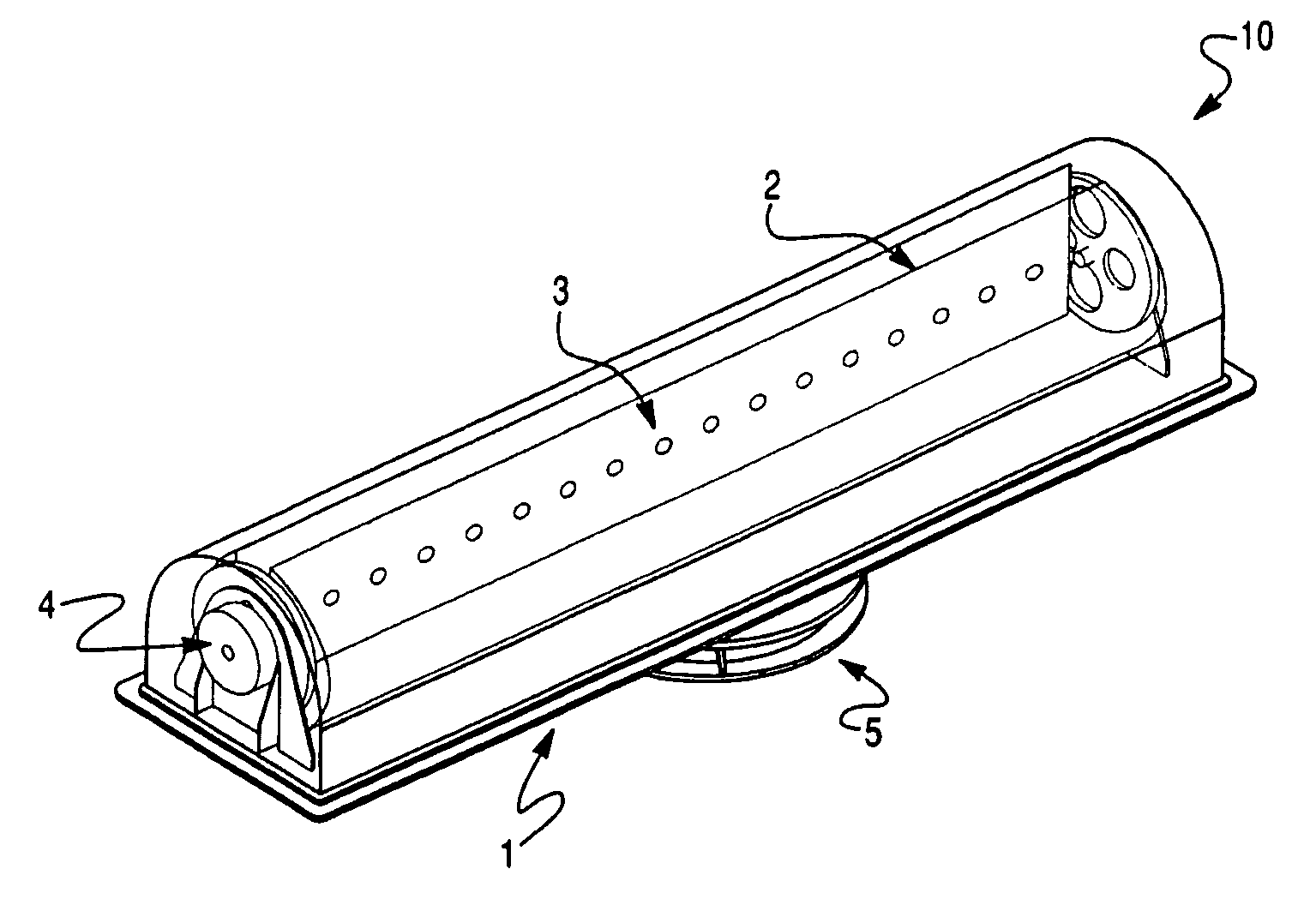
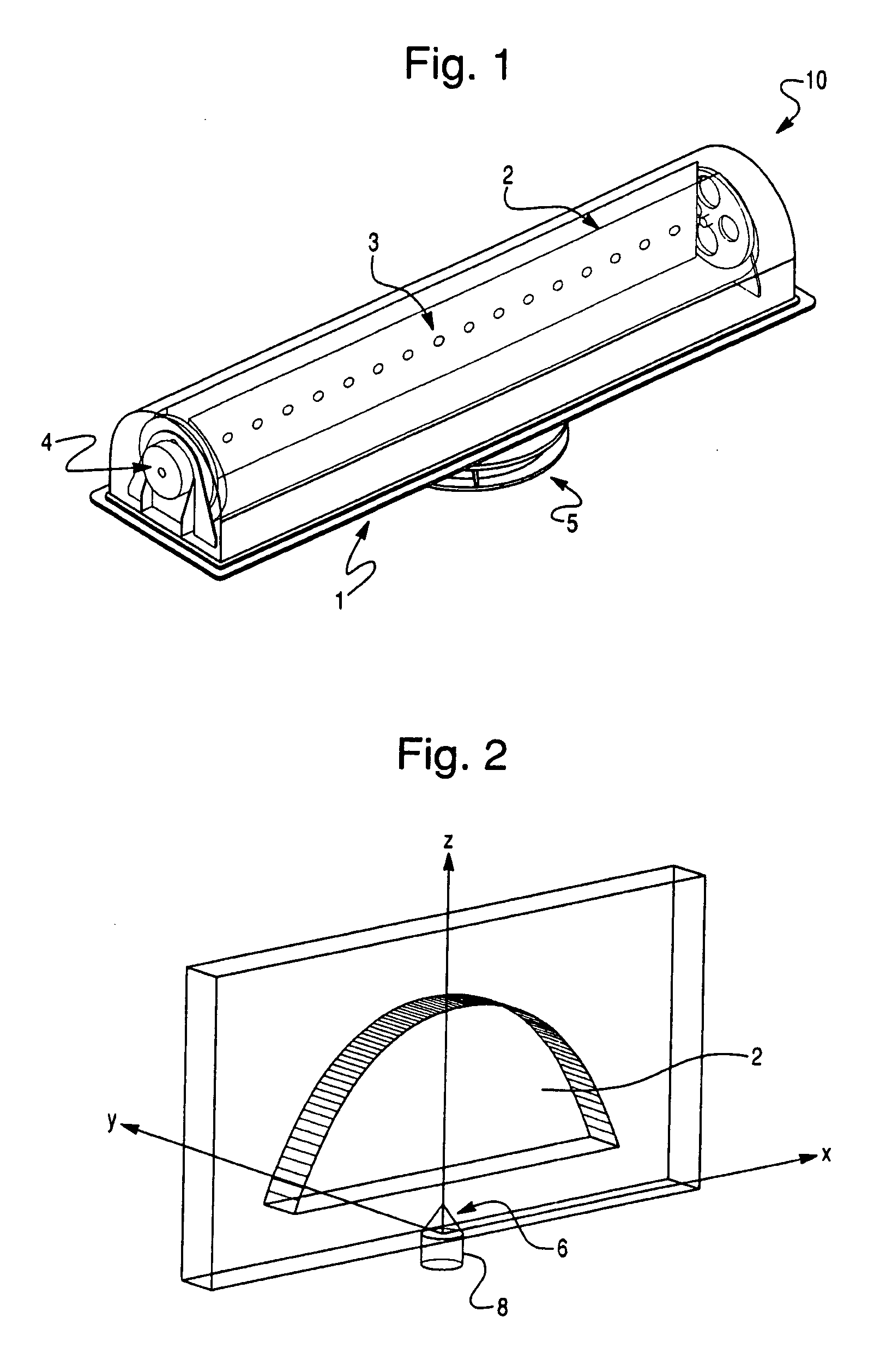
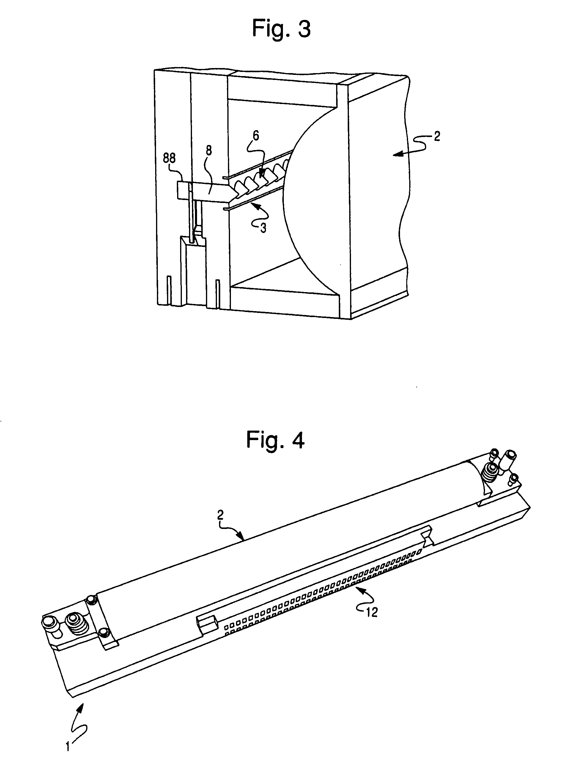
[0030]According to one embodiment of the present invention, a low profile active quasi-optic array phased antenna system is provided incorporating a one-dimensional phased array and collimating lens, which may be used for a number of different applications including vehicle mobile satellite communications. The system provides multiple band transmission and reception in a single aperture. The antenna system transmits and receives simultaneously with no mechanical alterations required to change bands. According to one embodiment of the present invention, the antenna system in...


PUM


Abstract

A phased array antenna device is described. The phased array antenna device includes at least one one-dimensional phased array of radiating elements arranged along an array direction, a lens, and a phase control element. The lens is arranged such that divergent beams from the radiating elements are collimated by the lens in a direction orthogonal to the array direction to produce a beam. The phase control element is configured to apply a linear phase gradient to the radiating elements thereby providing one-dimensional electronic beam steering for the antenna device. The antenna device may additionally include one or two mechanical positioners to mechanically move the at least one one-dimensional phased array in directions orthogonal to the array direction, where the phased array enables scanning along the array direction.

Description

CROSS-REFERENCE TO RELATED PATENT APPLICATIONS[0001]This application claims priority from U.S. Provisional Application Application 60 / 924,098, filed Apr. 30, 2007, incorporated herein by reference in its entirety.FIELD OF THE INVENTION[0002]Embodiments of the present invention relate generally to antennas. In particular, embodiments of the present invention relate to a low profile active quasi-optic phased array antenna.BACKGROUND OF THE INVENTION[0003]Conventionally there exist several types of communication antenna designs. These include the three-axis pedestal, the two-axis pedestal, and parallel mechanical plate scanning. The three-axis pedestal provides full hemispheric coverage without the “keyhole phenomenon,” but are large and complex and the required reflector needs multi-band mechanical radiating elements and mechanical linear polarization adjustments. The two-axis pedestal is less complex, but suffers from the drawback of periodic data outages from the keyhole phenomenon....

Claims


Application Information

Patent Timeline
Patent Type & Authority Applications(United States)
IPC IPC(8): H01Q19/06H01Q19/10
CPCH01Q13/10H01Q19/062H01Q21/08
Inventor KOH, CHRISTOPHER TZE-CHAONEWMAN, THOMAS ROBERTWHITNEY, KENT ARTHUR
Owner SMITHS INTERCONNECT INC
Why Eureka
Try Eureka