Method for fabricating reflective optical film and reflective polarizing film and method for fabricating the same

Inactive Publication Date: 2008-11-13
TAIWAN TFT LCD ASSOC +6
View PDF19 Cites 2 Cited by
  • Summary
  • Abstract
  • Description
  • Claims
  • Application Information

AI Technical Summary

Benefits of technology

[0017]Since the present invention utilizes different alignments and coatings of liquid crystal materials to perform coating of a phase retardation film such as λ/4 film and coating of CLC orderly. As a result, the problems with the more disordered alignment in the upper layer of CLC compared to that in the lower layer of CLC can be solved that poor optical performance and failure to show phase retardation caused by unidirectional alignment transferring into radial alignment within the phas

Problems solved by technology

Nevertheless, currently, the bonding of a polarizer to CLC and a λ/4 film relies on a rotating layer or 45 degree bonding, which are both considered as complicated and time-consuming fabrication processes.
On the ot

Method used


Image

  • Method for fabricating reflective optical film and reflective polarizing film and method for fabricating the same
  • Method for fabricating reflective optical film and reflective polarizing film and method for fabricating the same
  • Method for fabricating reflective optical film and reflective polarizing film and method for fabricating the same

Examples


Example

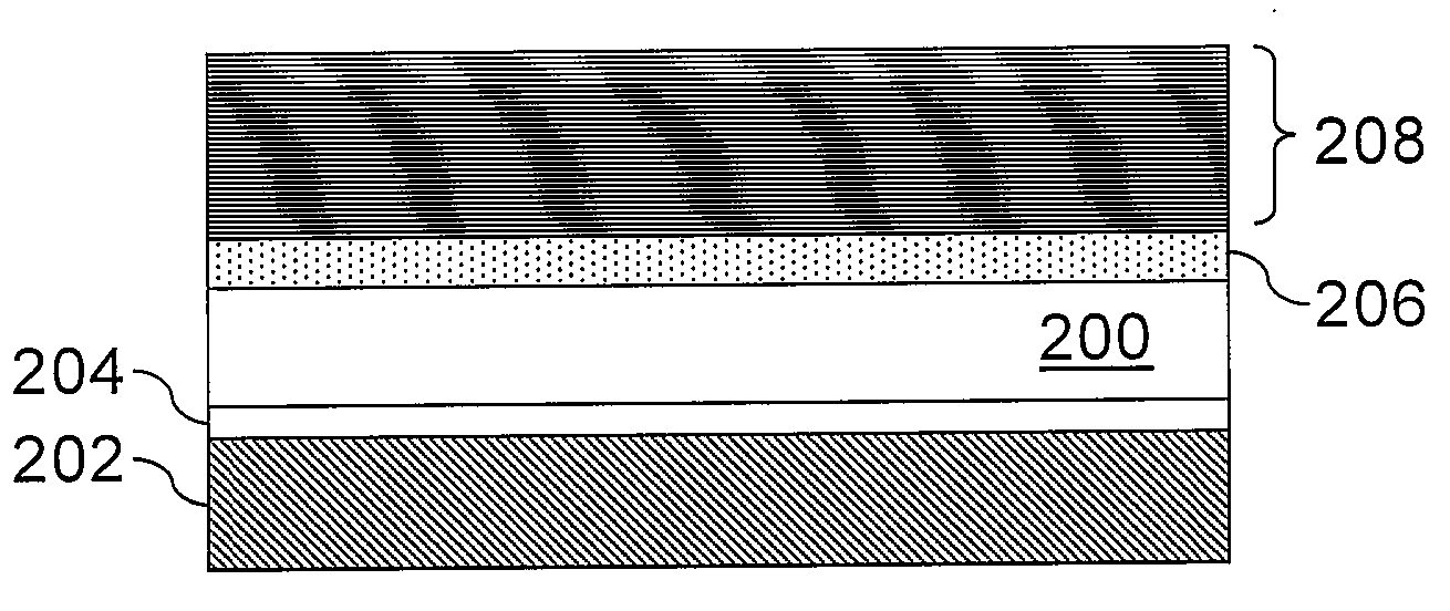
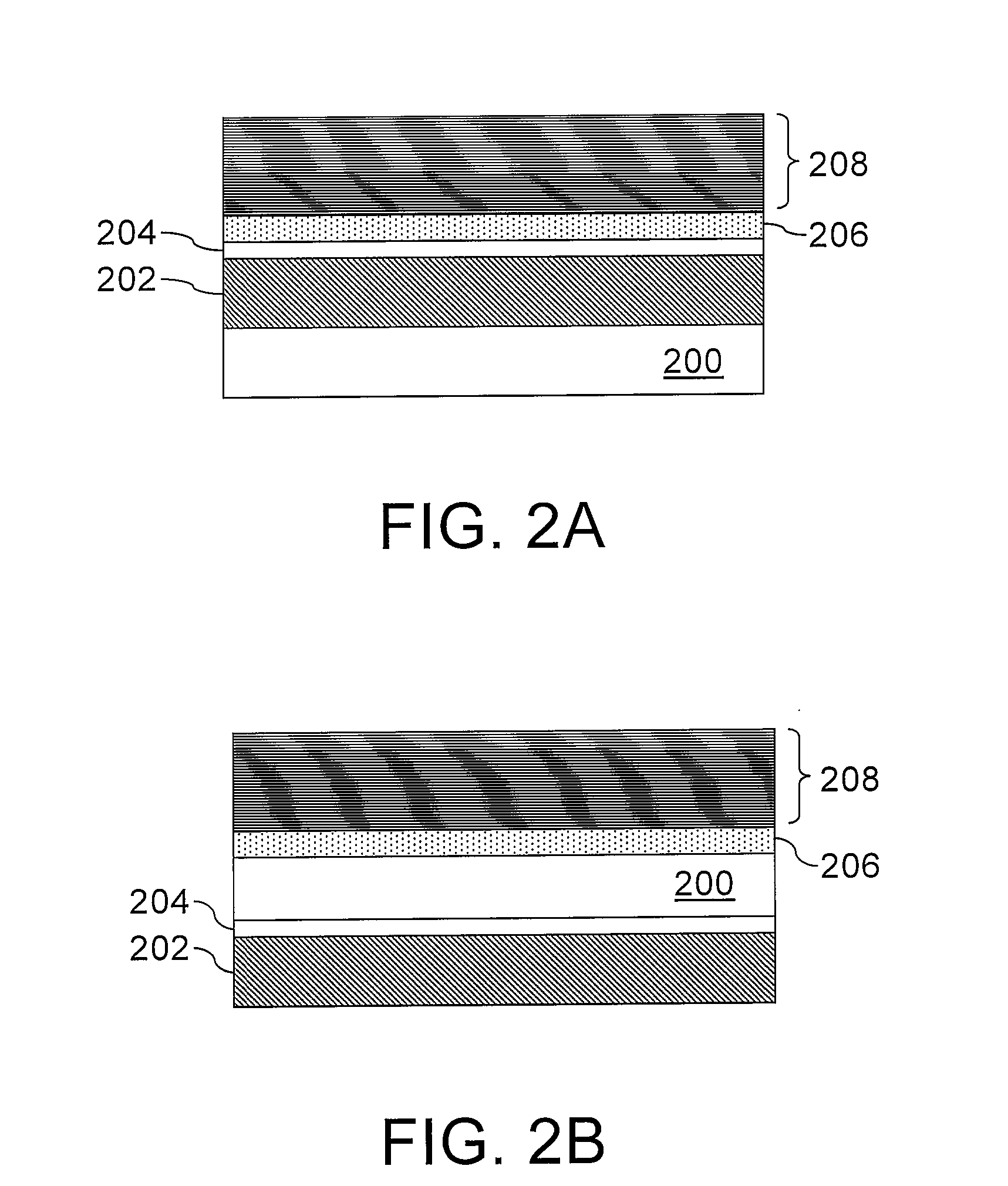
[0031]Please refer to FIG. 2A and FIG. 2B. According to the second embodiment, a reflective polarizing film includes a substrate 200, a polarizing film 202, a rotating layer 204, a phase retardation film 206 and a chloesteric liquid crystal (CLC) layer 208. Herein, the rotating layer 204 is formed by an ultra-thin layer of CLC having a thickness of less than 1 μm. Further, the phase retardation film is, for example, a λ / 4 film. The phase retardation film 206 and the polarizing film 202 are respectively disposed above and below the rotating layer 204. The CLC layer 208 is disposed on the phase retardation film 206. The substrate 200 may be disposed below the polarizing film 202 (as shown in FIG. 2A); or the substrate 200 may be disposed between the phase retardation film 206 and the rotating layer 204 (as shown in FIG. 2B). The substrate 200 may be a transparent substrate or an opaque substrate.

[0032]In the second embodiment, when the reflective polarizing film is applied in a displa...

Example

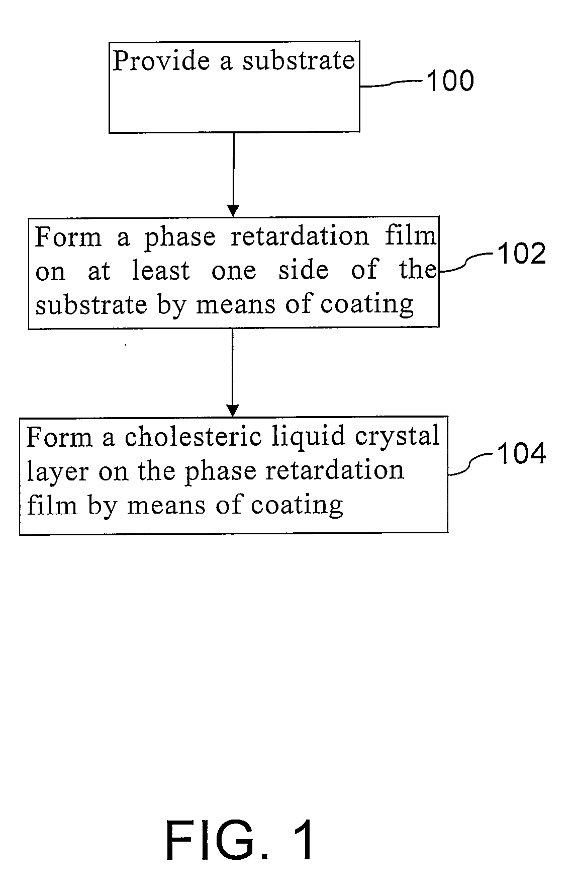
[0034]According to the third embodiment, a coating technique is used to form each layer on the substrate. Further, the phase retardation film is formed prior to the formation of the cholesteric liquid crystal (CLC) layer. Herein, according to FIG. 3A, the polarizing film is formed on the substrate (step 302), then the rotating layer is formed on the polarizing film (step 304), the phase retardation film is formed on the rotating layer (step 306), and the CLC layer is formed on the phase retardation film (step 308).

[0035]According to FIG. 3B, the phase retardation film is respectively formed on the two sides of the substrate (step 402), the rotating layer is formed on the two sides of the substrate (step 406), the CLC layer is formed on the phase retardation film (step 404), and the polarizing film is formed on the rotating layer (step 408).

[0036]Please refer to FIG. 3A and FIG. 3B. In steps 300 and 400, the substrate may be a transparent substrate or an opaque substrate. In steps 30...


PUM

PropertyMeasurementUnit
Lengthaaaaaaaaaa
Transparencyaaaaaaaaaa
Phaseaaaaaaaaaa

Abstract

A method for fabricating a reflective optical film is provided. A substrate is first provided. Next, a phase retardation film is formed on at least one side of the substrate by means of coating. Afterward, a cholesteric liquid crystal (CLC) layer is formed on the phase retardation film by means of coating. Hence, the conventional external bond fabrication process can be simplified. Further, the undesired optical results caused by the more disordered alignment in the upper layer of CLC being more disordered compared to that in the lower layer of CLC and the failure to display the compensation effect can be overcome.

Description

CROSS-REFERENCE TO RELATED APPLICATION[0001]This application claims the priority benefit of Taiwan application serial no.96116277, filed on May 8, 2007. All disclosure of the Taiwan application is incorporated herein by reference.BACKGROUND OF THE INVENTION[0002]1. Field of the Invention[0003]The present invention relates to a fabrication method of a reflective optical film, and a reflective polarizing film and a fabrication method thereof.[0004]2. Description of Related Art[0005]Generally, a liquid crystal display utilizes linear polarized light generated by two polarizing films to display images and the primary light source is a backlight module / the light is primarily provided by a backlight module. The backlight module generates light that travels through the first polarizing film to produce linear polarized light. Further, as the alignment of liquid crystal molecules twists in the liquid crystal display, brightness or darkness is produced after the light reaches the second polar...

Claims


Application Information

Patent Timeline
IPC IPC(8): G02B5/30B05D5/06G02B1/02
CPCG02B5/3016G02B5/305G02B5/3083
Inventor JENG, YUE-SHIHWU, YU-HSUNLIN, YEN-SHIH
Owner TAIWAN TFT LCD ASSOC
Why Eureka
Try Eureka