Method and Device for Controlling an Internal Combustion Engine

a technology of internal combustion engine and control device, which is applied in the direction of electrical control, process and machine control, instruments, etc., can solve the problems of significant pressure drop, and achieve the effect of good driveability

Active Publication Date: 2008-11-20
VITESCO TECH GMBH
View PDF4 Cites 16 Cited by
  • Summary
  • Abstract
  • Description
  • Claims
  • Application Information

AI Technical Summary

Benefits of technology

[0014]Also the required torque is frequently higher than the maximum torque that can be produced, particularly when there is an error

Problems solved by technology

Such an error can result in a very significant pressure drop, particularly in the case of a fuel

Method used


Image

  • Method and Device for Controlling an Internal Combustion Engine
  • Method and Device for Controlling an Internal Combustion Engine
  • Method and Device for Controlling an Internal Combustion Engine

Examples


Embodiment Construction

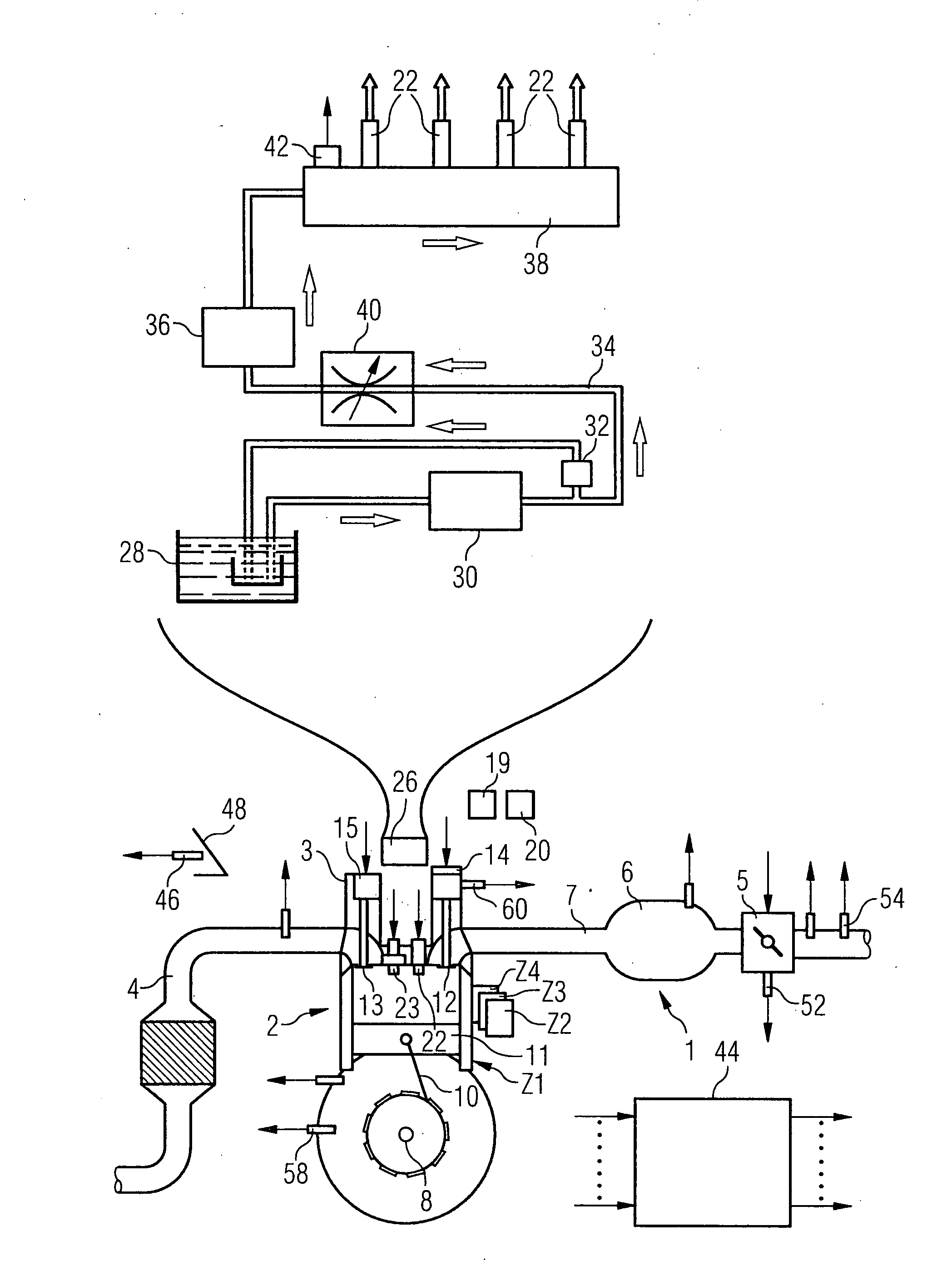
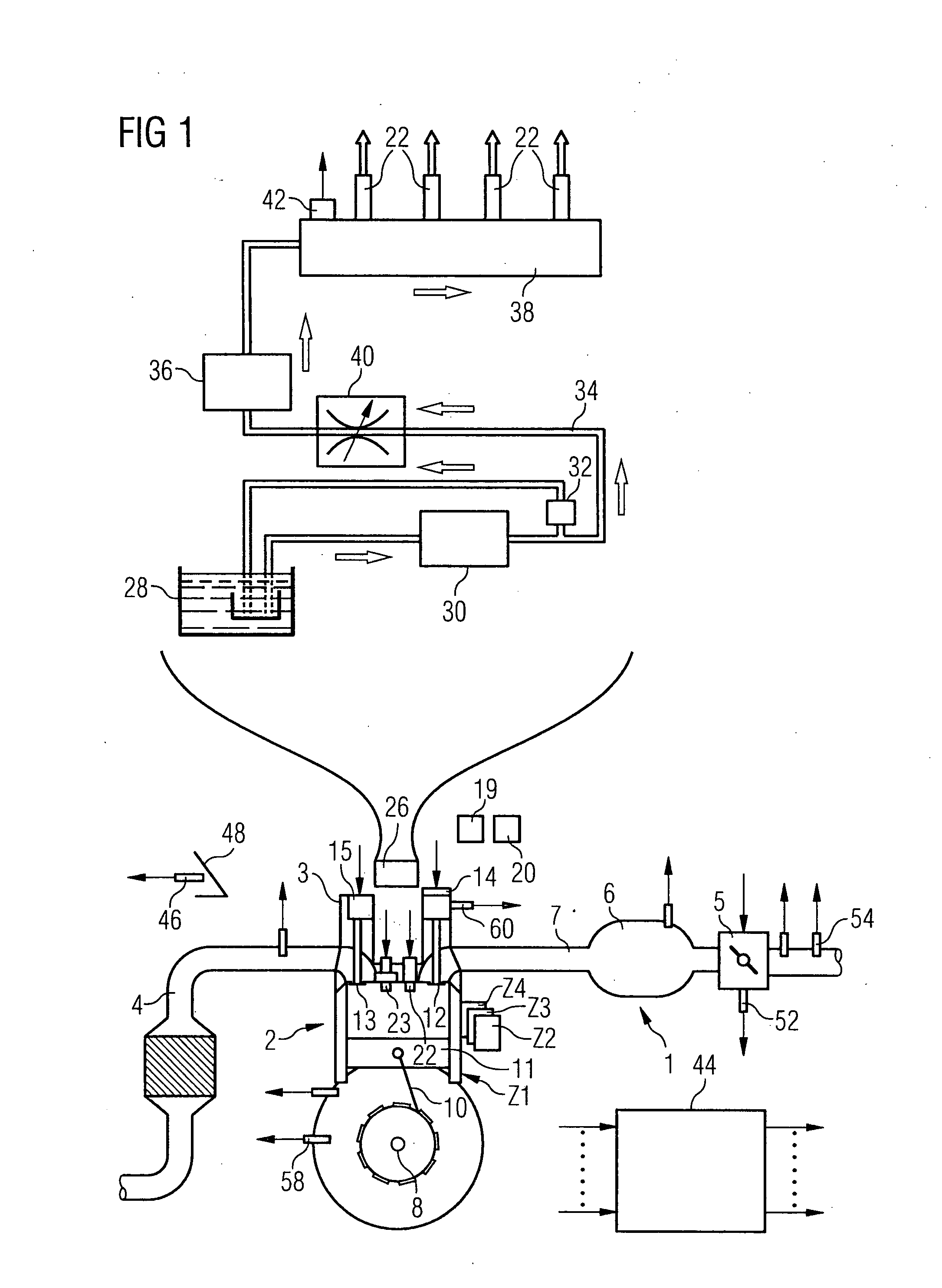
[0018]An internal combustion engine (FIG. 1) has an intake tract 1, an engine block 2, a cylinder head 3 and an exhaust gas tract 4. The intake tract 1 preferably has a throttle valve 5, also a manifold 6 and an intake pipe 7, which leads to a cylinder Z1 via an intake duct into the engine block 2. The engine block 2 also has a crankshaft 8, which is coupled via a connecting rod 10 to the piston 11 of the cylinder Z1.

[0019]The cylinder head 3 has a valve drive with a gas inlet valve 12, a gas outlet valve 13 and valve drives 14, 15. The valve drives 14, 15 have or are assigned a camshaft, having cams, which act on the gas inlet valve 12 and / or the gas outlet valve 13. A separate camshaft is preferably assigned respectively to the gas inlet valve 12 and the gas outlet valve 13.

[0020]A valve lift adjustment device 19 can also be provided, to change the lift pattern, allowing a low and high valve lift to be set for example. A phase adjustment device 20 can also be provided, by means of...


PUM


Abstract

An internal combustion engine is provided with at least one modulator for adjusting an air mass in a cylinder. It is also provided with an injection valve for metering fuel to which fuel is supplied via a fuel supply device. A maximum fuel quantity which can be metered to the cylinder per working stroke is determined. Depending on the maximum meterable fuel quantity, a maximum producible torque is determined. An air mass flow is determined depending on an air/fuel ratio to b adjusted and the maximum meterable fuel quantity is adjusted by controlling the at least one modulator for adjusting the air mass. The injection valve is controlled in accordance with the maximum meterable fuel quantity when the required torque is greater or equal the maximum producible torque.

Description

CROSS REFERENCE TO RELATED APPLICATIONS[0001]This application is the US National Stage of International Application No. PCT / EP2005 / 053942, filed Aug. 10, 2005 and claims the benefit thereof. The International Application claims the benefits of German application No. 10 2004 047 622.5 filed Sept. 30, 2004, both of the applications are incorporated by reference herein in their entirety.FIELD OF INVENTION[0002]The present invention relates to a method and a device for controlling an internal combustion engine.BACKGROUND OF THE INVENTION[0003]The performance and efficiency of internal combustion engines are subject to increasingly stringent requirements. Also the pollutant emissions produced by internal combustion engines have to be kept low due to strict legal provisions. To this end final control elements are provided, which allow a very high level of air delivery to be ensured over wide operating areas of the internal combustion engine. Injection valves are also used, to which fuel i...

Claims


Application Information

Patent Timeline
IPC IPC(8): F02D41/38
CPCF01L1/34F02D41/0002F02D41/221F02D2041/001F02D2041/2048F02D2250/26F02D2250/38F02M63/0225F02D41/38F02D41/22
Inventor ESER, GERHARDZHANG, HONG
Owner VITESCO TECH GMBH
Why Eureka
Try Eureka