Clothes iron storage rack

a technology for clothes irons and racks, which is applied in the field of storage racks for clothes irons, can solve the problems of unfavorable consumers, unfavorable consumers, and unsanitary, and achieve the effects of convenient transportation and hanging, simple and inexpensive, and convenient transportation

a technology for clothes irons and racks, which is applied in the field of storage racks for clothes irons, can solve the problems of unfavorable consumers, unfavorable consumers, and unsanitary, and achieve the effects of convenient transportation and hanging, simple and inexpensive, and convenient transportation

US20080289228A1Inactive Publication Date: 2008-11-27JONES RUTH B +2

Image

  • Clothes iron storage rack
  • Clothes iron storage rack

Examples


Embodiment Construction

, particularly, when such description is taken in conjunction with the attached drawing figures and with the appended claims.

BRIEF DESCRIPTION OF THE DRAWINGS

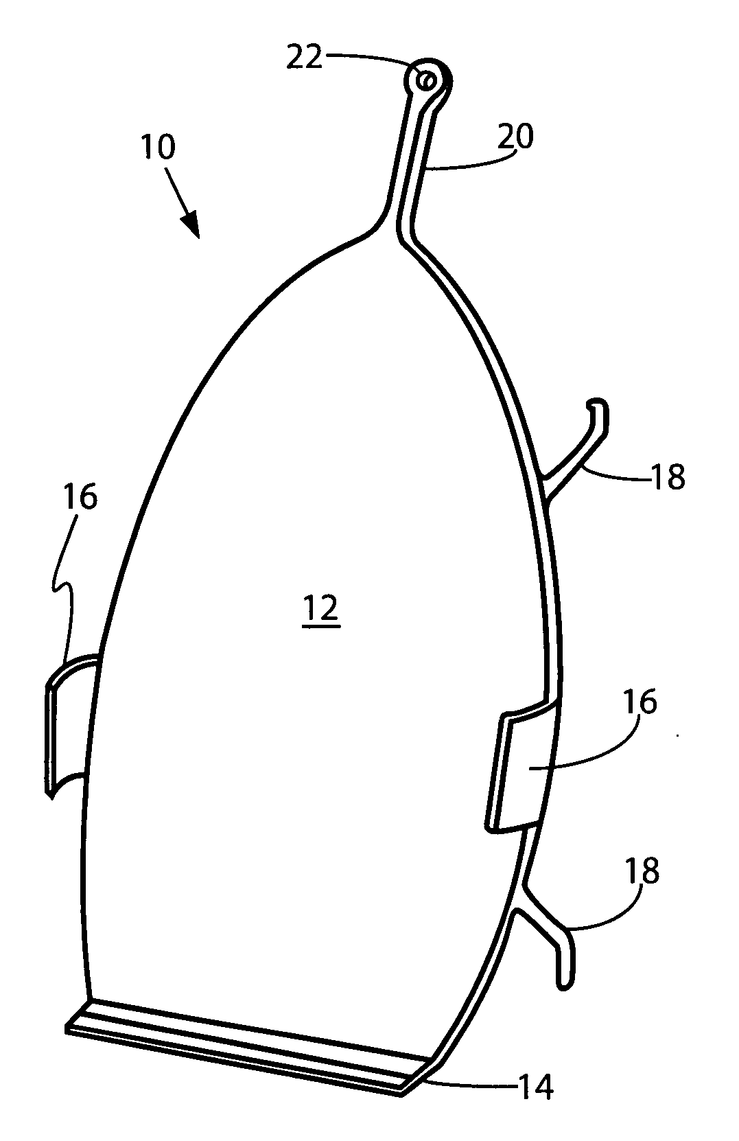
[0010]FIG. 1 is a perspective view of an embodiment of the pressing iron holder.

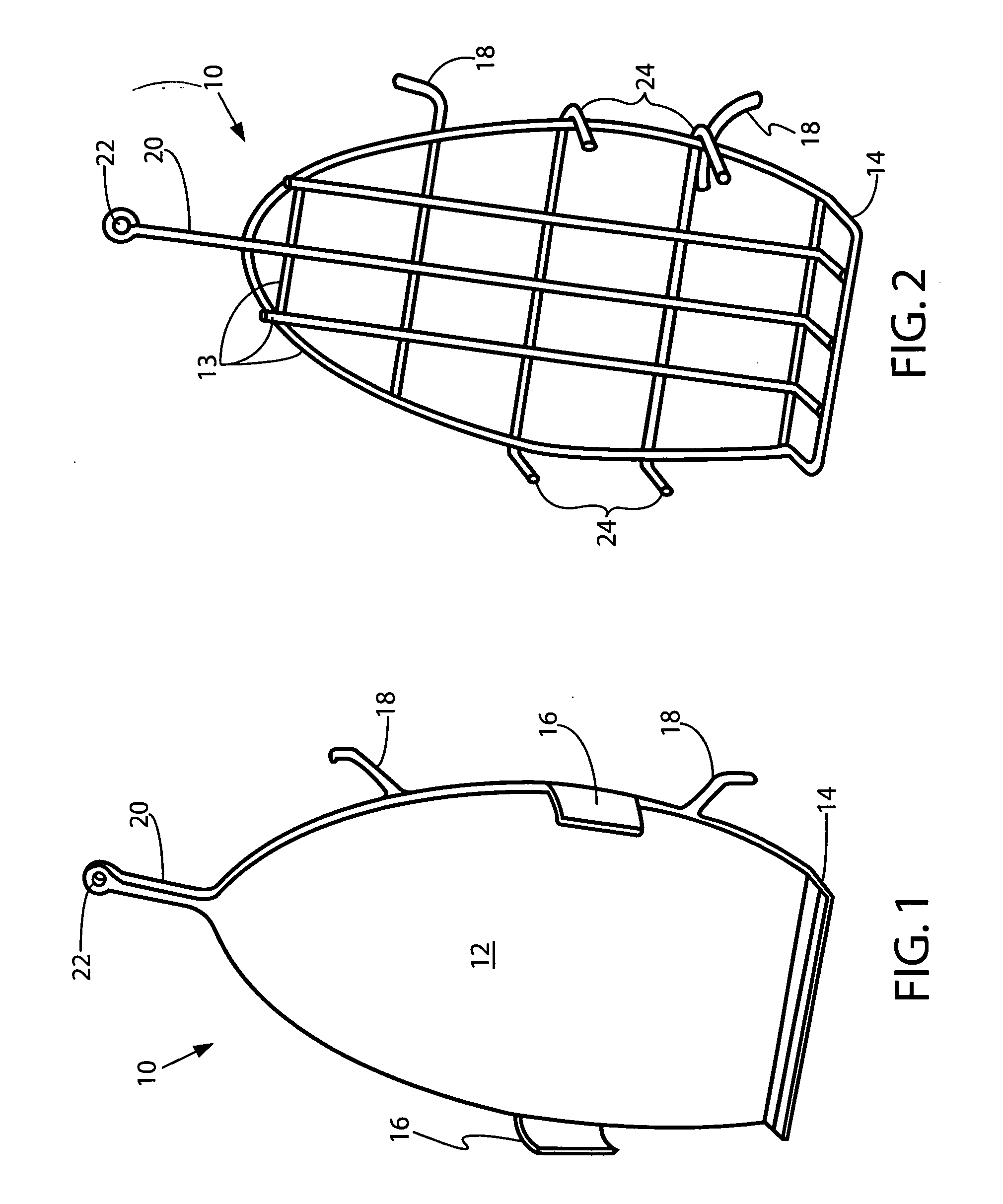
[0011]FIG. 2 provides a perspective view of an alternative embodiment of the present invention.

DETAILED DESCRIPTION OF A PRESENTLY PREFERRED AND VARIOUS ALTERNATIVE EMBODIMENTS OF THE INVENTION

[0012]Prior to proceeding to the more detailed description of the present invention it should be noted that, for the sake of clarity and understanding, identical components which have identical functions have been identified with identical reference numerals throughout the several views illustrated in the drawing figures.

[0013]Referring initially to FIG. 1, the present invention is shown, generally as 10, in a perspective view. A solid, planar base plate 12 is shaped and sized similar to that of a common electrical pressing iron. At the widest point, its width...


PUM


Abstract

A pressing iron holder for electric clothing irons includes a substantially planar base defining a blunt butt end, a top end, and two side edges, and a flange is fixedly attached substantially perpendicular to the planar base proximal the butt end. Additional features are cord retention protrusions from one of the two side edges for neatly storing the power cord, at least one semi-rigid retaining clip fixedly attached proximal midpoint of each side edge, and a grasping / hanging extension at the top end.

Description

CROSS REFERENCE TO RELATED APPLICATION[0001]This patent application is related to and claims priority from U.S. Provisional Patent Application Ser. No. 60 / 931,882 filed May 25, 2007.FIELD OF THE INVENTION[0002]The present invention relates, in general, to storage of heated irons after use, and, more particularly, this invention relates to storage of electric clothes pressing irons and their cords.BACKGROUND OF THE INVENTION[0003]Prior to the conception and development of the present invention, clothes pressing irons are typically stored after use either upright or horizontally on the horizontal ironing board with the unplugged cord dangling over the edges of the board. This poses a safety hazard besides being unsightly.[0004]A multitude of devices for storing pressing irons have been disclosed in the prior art. A number of these are wall mounted holders with built-in cord supports as shown, for example, in U.S. Pat. Nos. 6,116,550 and 7,004,433. Others focus on insulating the hot ir...

Claims


Application Information

Patent Timeline
27 Nov 2008
Publication
US20080289228A1
IPC
D06F75/40
CPC
D06F79/02
Inventors
JONES, RUTH B.; JONES, SCOTT A.