Screen printing apparatus and screen printing method

a screen printing and printing apparatus technology, applied in the direction of inking apparatus, circuit inspection/indentification, conductive pattern formation, etc., can solve the problems of uneven not necessarily accurate holding positions of individual substrates,

Active Publication Date: 2008-11-27
PANASONIC CORP
View PDF11 Cites 26 Cited by
  • Summary
  • Abstract
  • Description
  • Claims
  • Application Information

AI Technical Summary

Benefits of technology

[0027]According to the present invention, the feedback data supplying step for supplying feedback data to improve the positional deviation state of a soldering paste obtains a plurality of average values of individual positional deviation quantities, which indicates the average value of the positional deviation quantity for each individual substrate, and then carries out a calculation for supplying feedback data, by which a mean value of the maximum value and the minimum value is obtained, if the deviation value indicating a difference between the maximum value and the minimum value of a plurality of average values of individual positional deviations is less than or equal to the tolerance value, whereby it is possible to carry out feedback of appropriate printing positions by correcting the positioning parameters of a mask plate based on the obtained mean values even in a case where a specified individual substrate greatly slips due to a certain cause in comparison with the other individual substrates.

Problems solved by technology

However, if an inspection function of a conventional electronic component mounting line including the related art example described above is applied to a component mounting mode in which such a plurality of individual substrates are held on the carrier, the following problems are brought about.
That is, a plurality of individual substrates are not necessarily held in accurate positions set in advance in a carrier when holding these individual substrates on the carrier.
Usually, the holding positions thereof become uneven in a specified range.
Where a specified individual substrate greatly slips due to a certain cause in comparison with the other substrates and is in an abnormal state, if the printing position is corrected in a printing device using soldering position information obtained by the print inspection device as it is, incorrect data resulting from the abnormal state is brought in as feedback data.
Thus, in the conventional screen printing apparatus, there may be cases where appropriate printing position data cannot be fed back in a component mounting mode in which a plurality of individual substrates are held on the carrier.

Method used


Image

  • Screen printing apparatus and screen printing method
  • Screen printing apparatus and screen printing method
  • Screen printing apparatus and screen printing method

Examples


Embodiment Construction

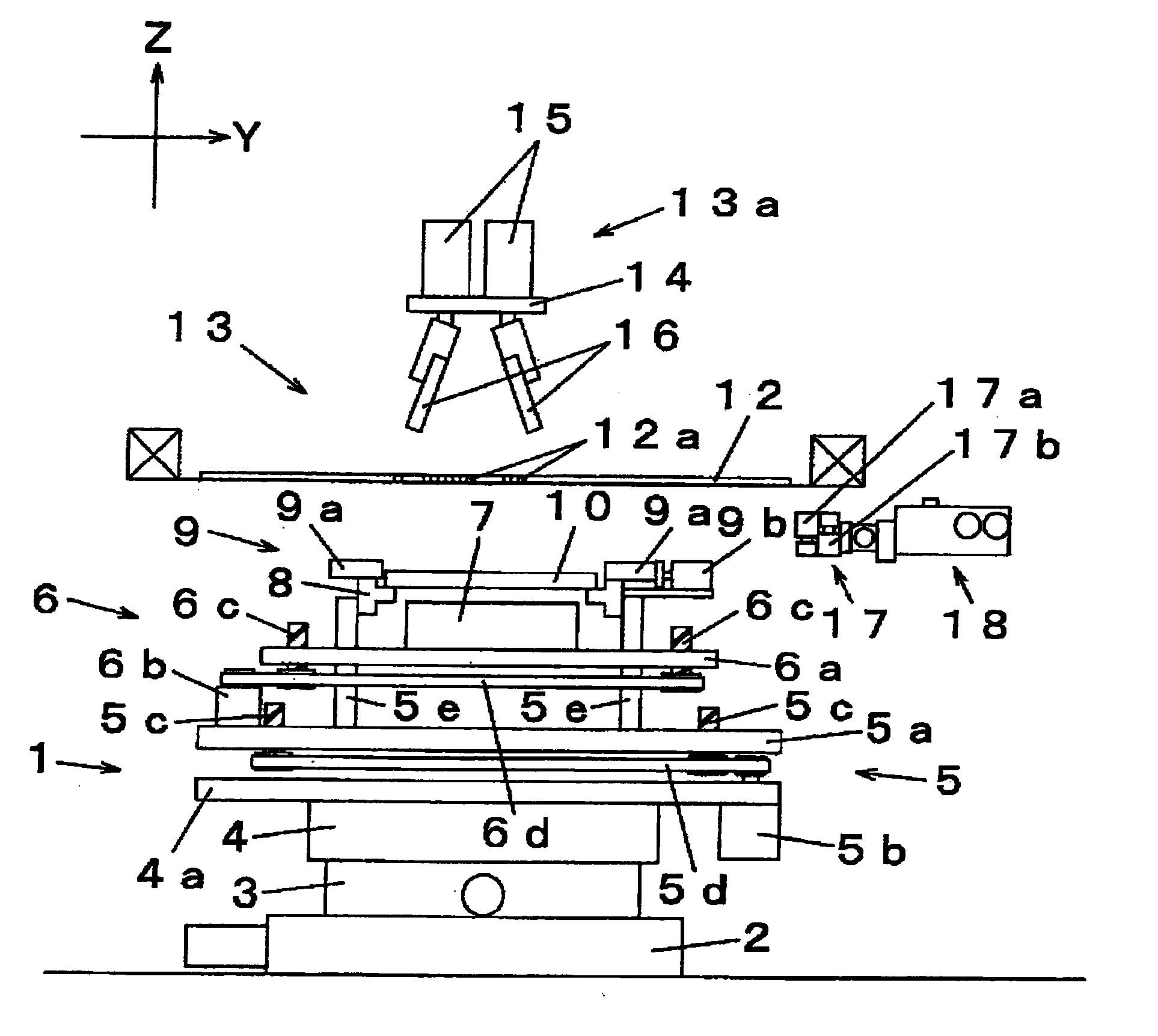
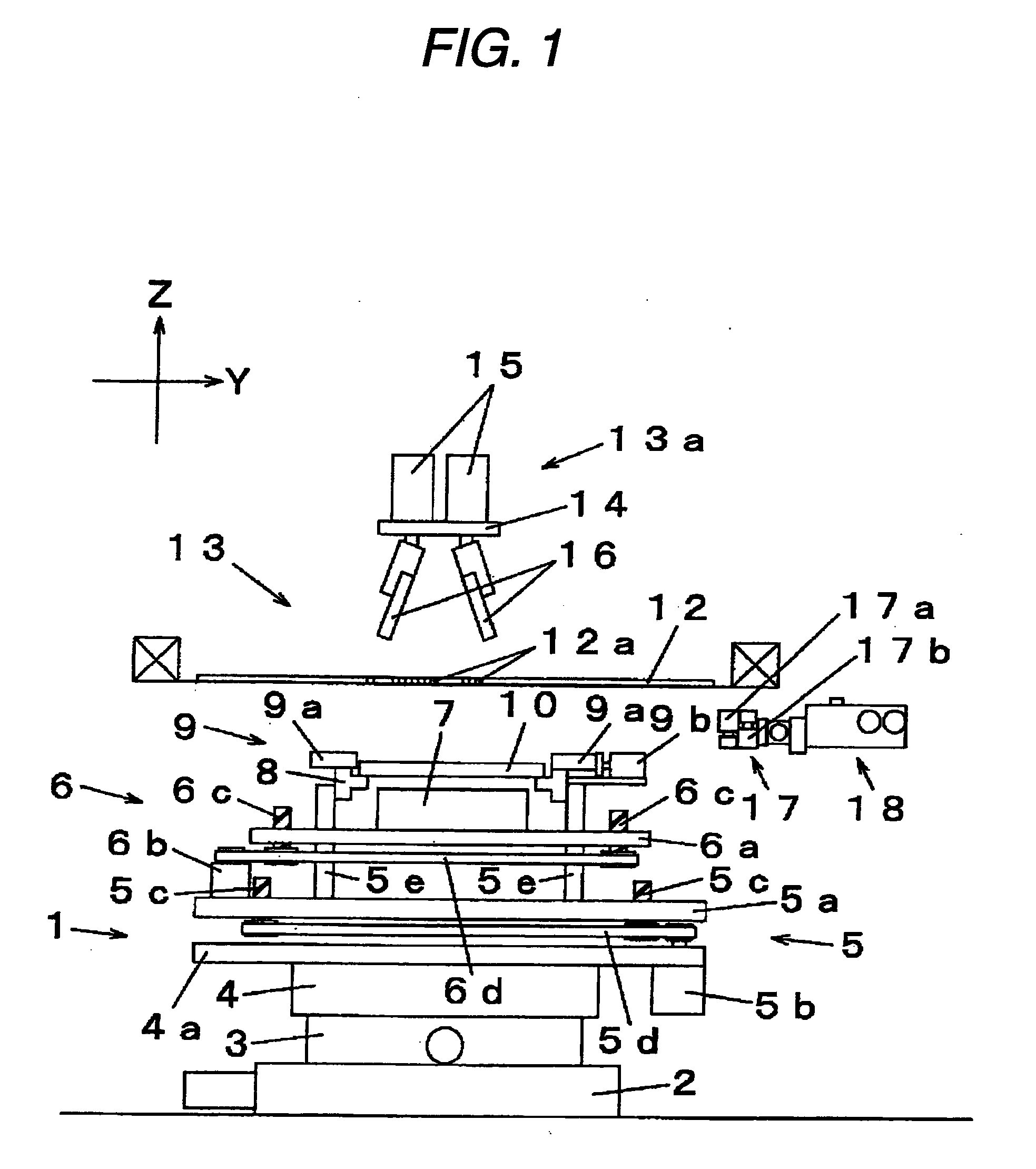
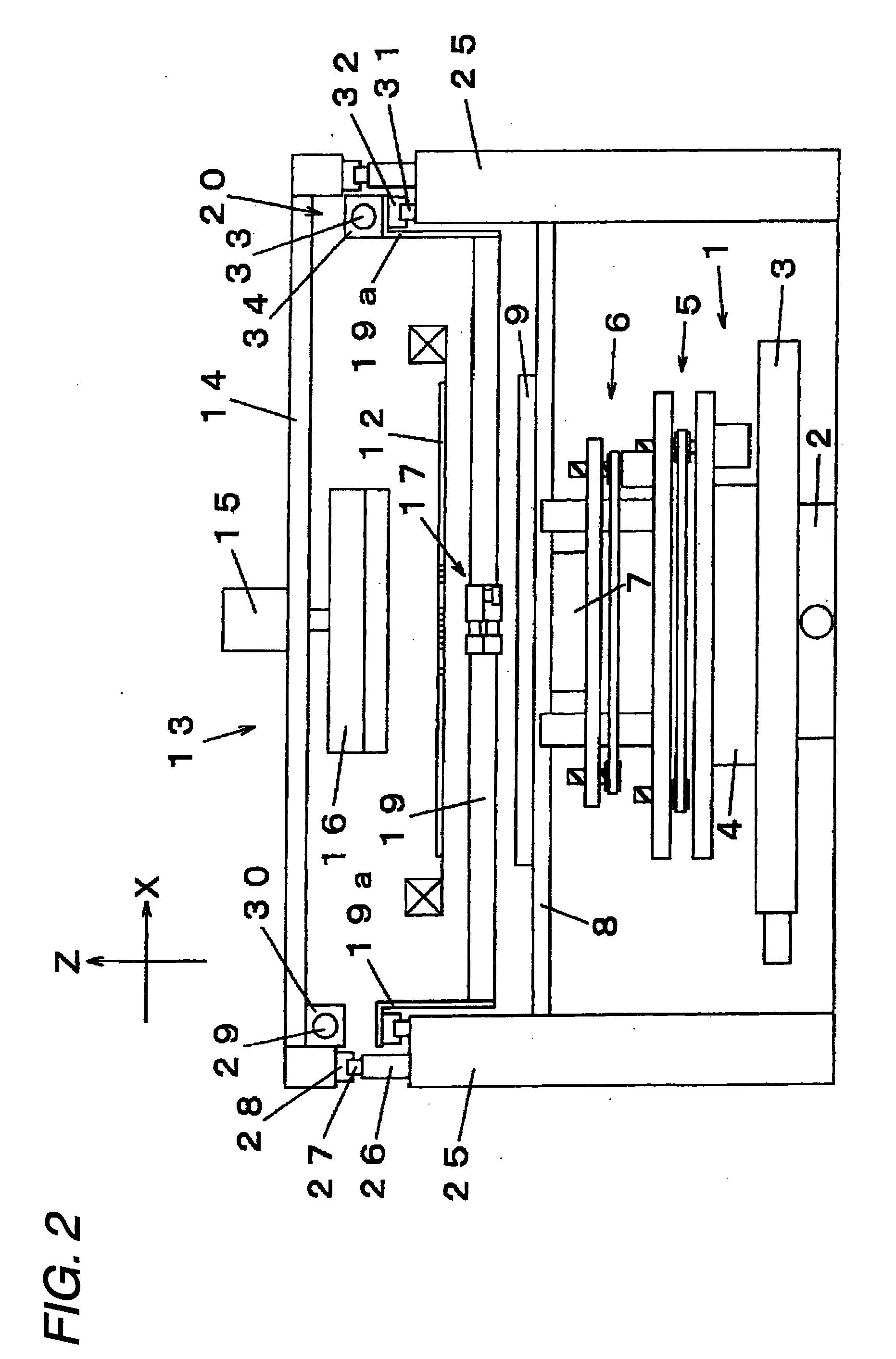
[0036]Next, a description is given of an embodiment of the present invention with reference to the drawings. FIG. 1 is a front elevational view showing a screen printing apparatus according to one embodiment of the present invention, FIG. 2 is a side elevational view showing a screen printing apparatus according to one embodiment of the present invention, FIG. 3 is a plan view showing a screen printing apparatus according to one embodiment of the present invention, FIGS. 4A to 4C are schematic views showing individual substrates and mask plates in a screen printing apparatus according to one embodiment of the present invention, FIG. 5 is a block diagram showing a configuration of a control system of a screen printing apparatus according to one embodiment of the present invention, FIG. 6 is a schematic view showing soldering position deviation data in a screen printing method according to one embodiment of the present invention, FIG. 7 and FIG. 8 are schematic views showing a feedbac...


PUM


Abstract

In supply of feedback data to improve a positional deviation quantity and a deviation state of a soldering paste printed on individual substrates held on the carrier, a plurality of average values of individual positional deviation for each of the individual substrates are obtained, and then, if the deviation value ΔM indicating a difference between the maximum value Mmax and the minimum value Mmin of the plurality of average values M of individual positional deviation is less than or equal to the tolerance value Δ(t), an intermediate value of the maximum value Mmax and the minimum value Mmin is obtained, and the positioning parameters of the mask plate and the carrier are corrected based on the intermediate value (Mmax+Mmin) / 2.

Description

BACKGROUND OF THE INVENTION[0001]1. Field of the Invention[0002]The present invention relates to a screen printing apparatus and a screen printing method for printing a soldering paste with respect to a plurality of individual substrates held on a carrier.[0003]2. Related Art[0004]An electronic component mounting system for manufacturing a component-mounted substrate by soldering and connecting electronic components on a substrate is configured by connecting a plurality of a solder printing apparatus, an electronic component mounter, a reflow apparatus, etc. In such an electronic component mounting system, inspection devices are disposed between respective apparatuses for the purpose of carrying out quality control at high reliability, and are given a function of automatically determining suitability of component mounting operations (For example, refer to Japanese Patent No. 3344739).[0005]In the example shown by Japanese Patent No. 3344739 described above, in a component mounted su...

Claims


Application Information

Patent Timeline
Patent Type & Authority Applications(United States)
IPC IPC(8): B05C9/08B41M1/12
CPCB41F15/0818B41F15/26B41F33/0036H05K1/0269H05K3/0008H05K3/1216H05K3/3484H05K2203/163H05K3/3485B41F15/0813B41F15/42H05K3/12
Inventor INOUE, MASAFUMIKIKUTSUGI, FUMIOKIHARA, MASAHIRO
Owner PANASONIC CORP
Why Eureka
Try Eureka