Foot of walking robot and walking robot having the same

a technology of walking robots and feet, applied in the field of walking robots, can solve the problems of reducing the degree of freedom, walking robots cannot walk smoothly, walking robots may lose balance and fall, etc., and achieve the effect of minimizing the tilting of the sole of the foo

Inactive Publication Date: 2008-12-04
SAMSUNG ELECTRONICS CO LTD
View PDF6 Cites 20 Cited by
  • Summary
  • Abstract
  • Description
  • Claims
  • Application Information

AI Technical Summary

Benefits of technology

[0009]Therefore, one aspect of the embodiments is to provide a foot of a walking robot, which minimizes tilting of the sole of the foot even when the walking robot walks on the uneven ground, and a walking robot having the same.
[0010]Another aspect of the embodiments is to provide a foot of a walking robot, which reduces a degree of freedom to easily control the walking of the robot, and alleviates impact applied to the foot in various directions when landing, and a walking robot having the same.

Problems solved by technology

Further, the foot of the walking robot has a simple shape, and thus reduces a degree of freedom, thereby allowing the walking of the robot to be easily controlled.
However, since the foot of the walking robot has a flat sole, the sole of the foot is tilted when the walking robot walks on the uneven ground or the ground having obstacles, and thus the walking robot cannot walk smoothly.
In the case that the sole of the foot is severely tilted, the walking robot may lose its balance and fall.
Further, the foot of the walking robot has an impact absorbing part with a small thickness at the sole, and thus cannot effectively absorb an impact applied perpendicularly to the sole of the foot.
Accordingly, in the case that an unexpected great impact is applied to the sole of the foot, the impact is transmitted to the ankle of the robot and causes damage to a multi-axis force and torque (F / T) sensor installed at the ankle.

Method used


Image

  • Foot of walking robot and walking robot having the same
  • Foot of walking robot and walking robot having the same
  • Foot of walking robot and walking robot having the same

Examples


Embodiment Construction

[0032]Reference will now be made in detail to the embodiments, examples of which are illustrated in the accompanying drawings, wherein like reference numerals refer to like elements throughout. The embodiments are described below to explain the present invention by referring to the annexed drawings.

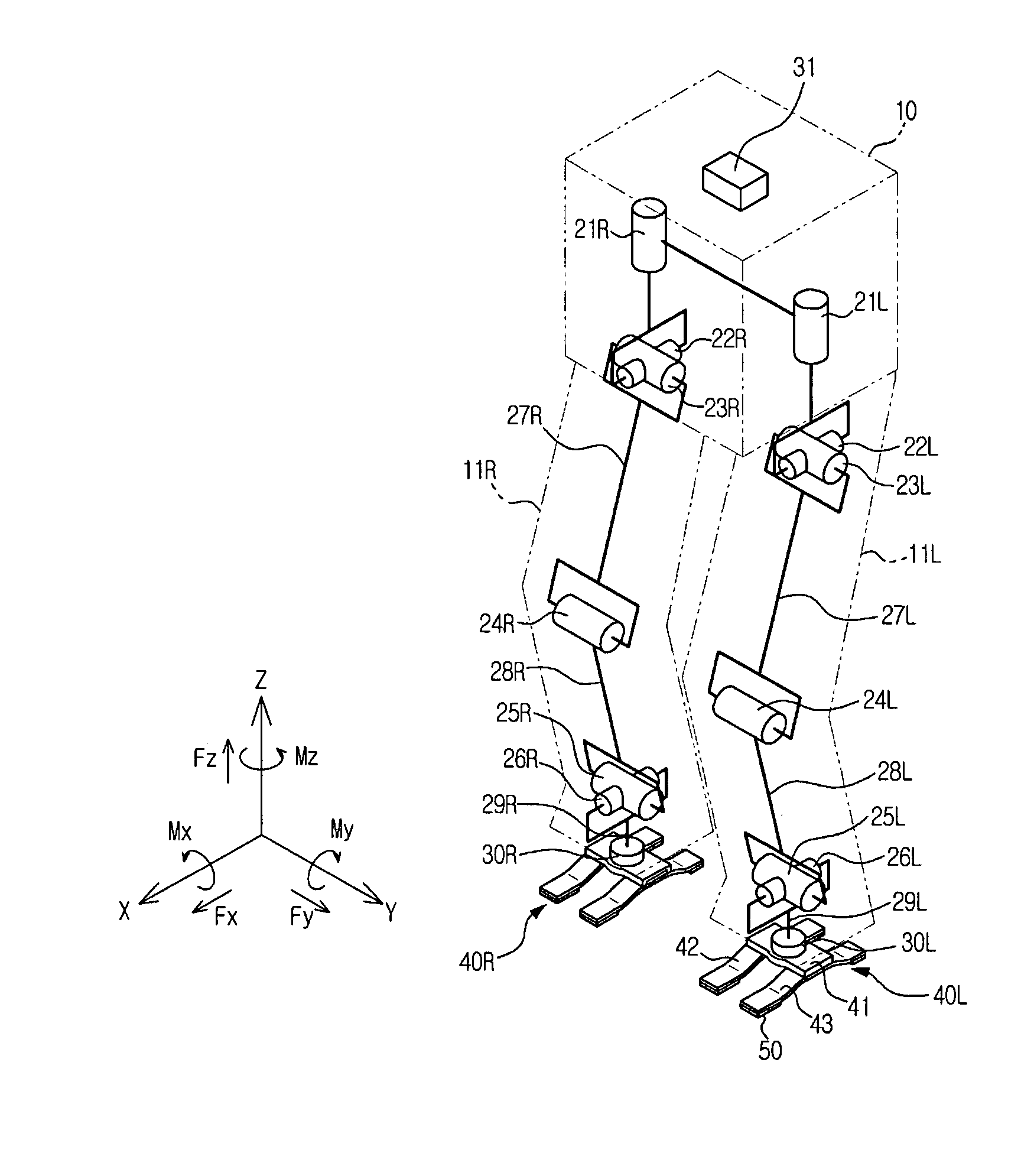
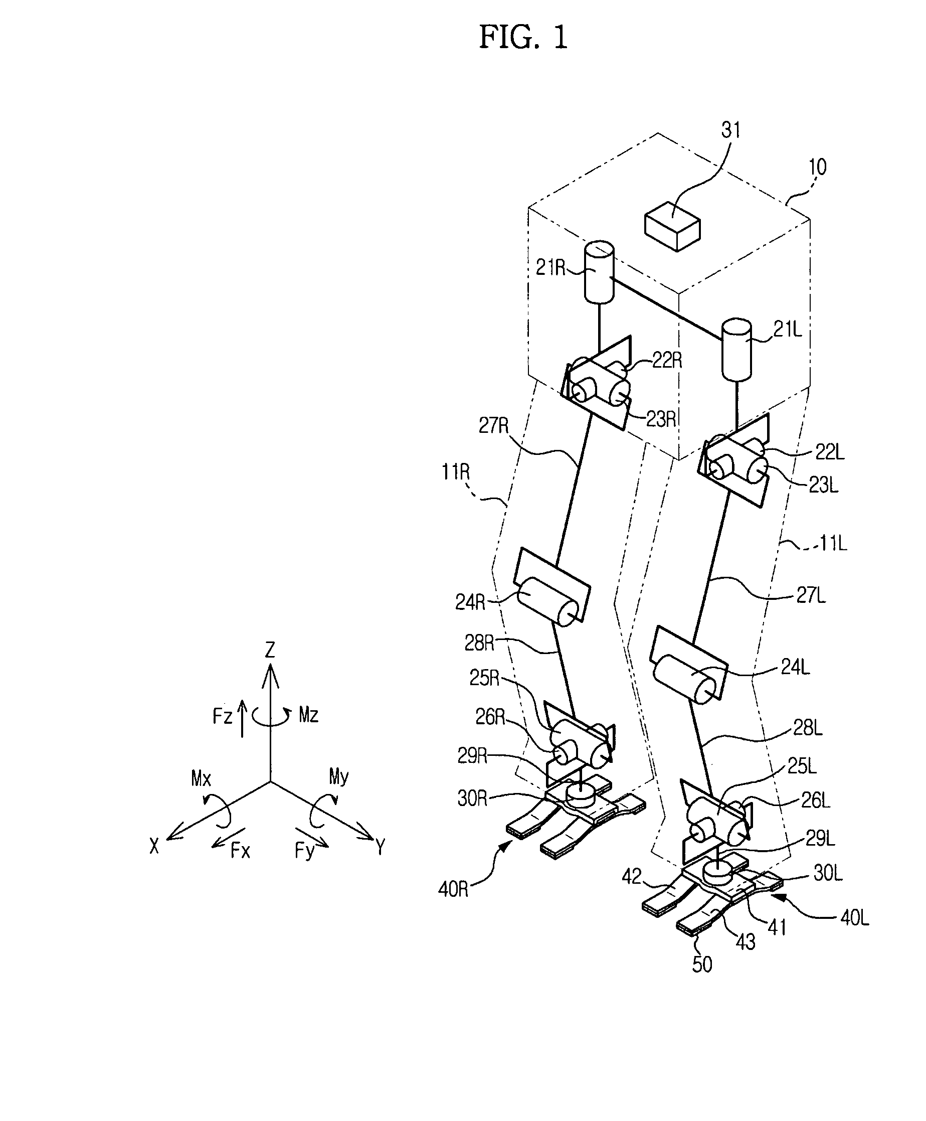
[0033]FIG. 1 is a perspective view schematically illustrating feet and legs of a walking robot, to which the present embodiments are applied. As shown in FIG. 1, the walking robot includes a body 10, and two legs 11L and 11R respectively connected to both sides of the lower part of the body 10.

[0034]Each of the two legs 11L and 11R includes six joints in order to walk. That is, the two legs 11L and 11R respectively include joints 21L and 21R installed at a hip of the body 10, each to swivel the corresponding leg 11L or 11R around a Z axis, i.e., in a direction of gravity, joints 22L and 22R, each for roll rotation of the hip around an X axis, joints 23L and 23R, each for pitch rotation of...


PUM


Abstract

Disclosed are a foot of a walking robot, which minimizes tilting of a sole of the foot and reduces a degree of freedom to easily control the walking of the robot, and a walking robot having the same. The foot includes a frame connected to a lower portion of a leg of the walking robot; and a plurality of impact absorbing plates having elasticity respectively connected to two sides of the frame such that the impact absorbing plates are separated from each other. Each of the impact absorbing plates includes a separation part connected to the frame and separated from a ground surface, a front ground part extended forward from the separation part and contacting the ground surface, and a rear ground part extended backward from the separation part and contacting the ground surface.

Description

CROSS-REFERENCE TO RELATED APPLICATIONS[0001]This application claims the benefit of Korean Patent Application No. 2007-0053167, filed May 31, 2007, in the Korean Intellectual Property Office, the disclosure of which is incorporated herein by reference.BACKGROUND[0002]1. Field[0003]The present invention relates to a walking robot, and more particularly, to a foot of a walking robot, which alleviates an impact applied to the foot when walking and minimizes an overthrow of the robot, and a walking robot having the same.[0004]2. Description of the Related Art[0005]A foot of a walking robot serves to provide a driving force through friction with the ground so that the robot can walk as well as support the weight of the body of the robot transmitted through a leg. This foot of the walking robot must alleviate an impact applied thereto when landing and achieve stable walking. Thus, research on feet of walking robots has been carried out.[0006]Honda Motor Co., Ltd. in Japan has developed a ...

Claims


Application Information

Patent Timeline
Patent Type & Authority Applications(United States)
IPC IPC(8): B62D57/00
CPCB25J19/0091B62D57/032
Inventor PARK, JOONG KYUNGPARK, TAE WONYOON, JI WON
Owner SAMSUNG ELECTRONICS CO LTD
Why Eureka
Try Eureka