
Environmental scanning and image reconstruction thereof

a technology of environment scanning and image reconstruction, applied in the direction of instruments, measurement devices, optics, etc., can solve the problems of time-consuming process, difficult movement, placement, and inefficient 3d measurement of long and narrow shafts and similar structures

Pending Publication Date: 2022-02-17
FARO TECH INC
View PDF0 Cites 0 Cited by
  • Summary
  • Abstract
  • Description
  • Claims
  • Application Information

AI Technical Summary

Benefits of technology

The patent describes a scanning system that can be used to measure the position of an object. To ensure accurate measurements, the system includes a stabilizer that prevents the scanner from tilting too much in relation to the support structure. This stabilizer can be positioned between the scanner and the support structure. By minimizing this tilt, the scanning system can operate more effectively and produce accurate results.

Problems solved by technology

Highly precise and efficient 3D measurement of long and narrow shafts and similar structures can be a challenge.
Such movement, placement, and scanning can be a time-consuming process.

Method used


Image

  • Environmental scanning and image reconstruction thereof
  • Environmental scanning and image reconstruction thereof
  • Environmental scanning and image reconstruction thereof

Examples


Embodiment Construction

[0035]Embodiments of the present disclosure provide improved scanning of shafts and similar structures using a single scanner configured to move through the structure and take continuous scans.

[0036]It should be appreciated that while embodiments herein may refer to a particular type of measurement device, such as a laser scanner for example, this is for example purposes and the claims should not be so limited. In other embodiments, other types of measurement devices that are configured to measure a surface or an area may be used. These measurement devices include, but are not limited to: triangulation scanners, line scanners, flying spot scanners, structured light scanners (coded or uncoded), laser line probes, time of flight scanners, and laser trackers.

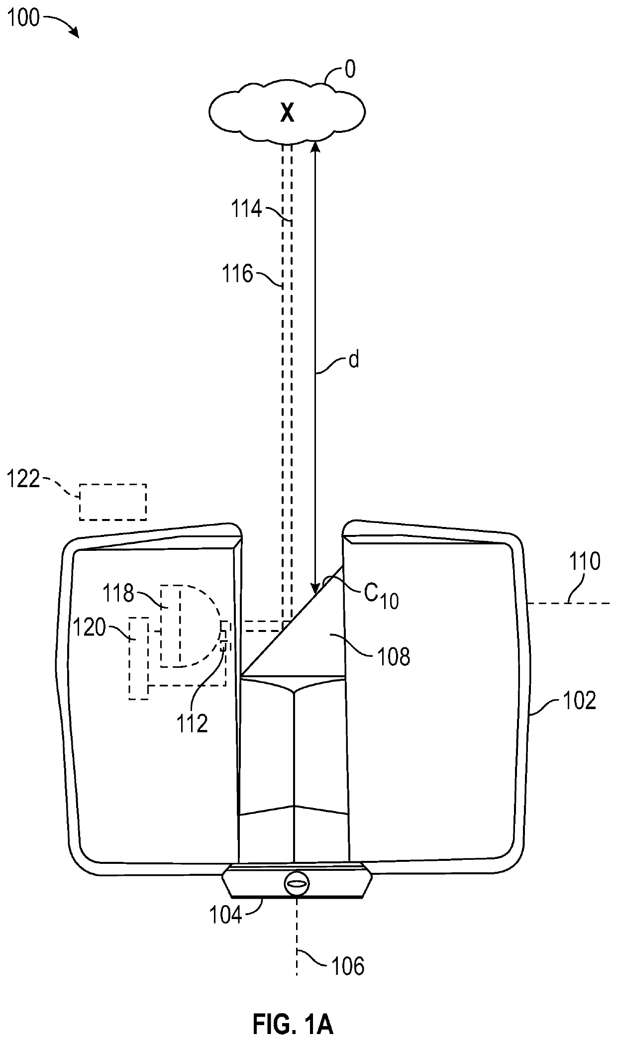
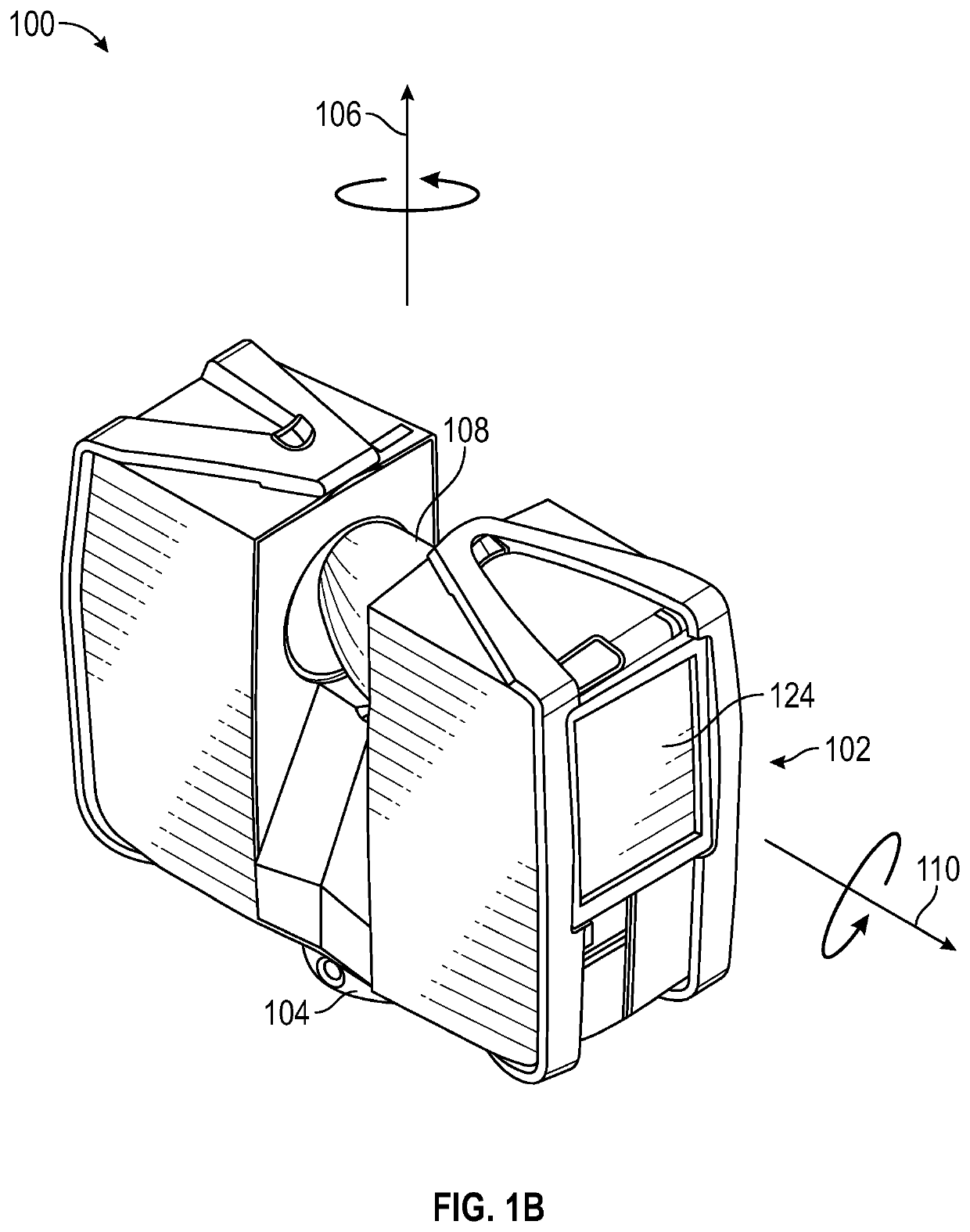
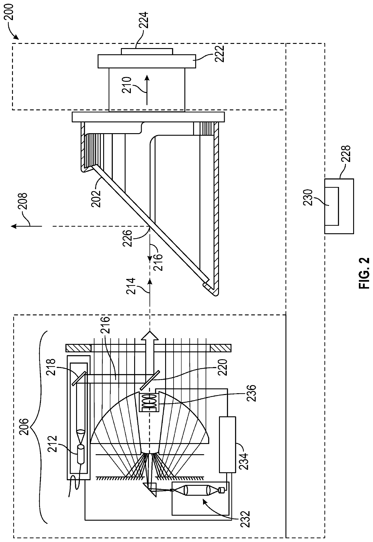
[0037]Referring to FIGS. 1A-1B, a 3D scanner 100 (e.g., a laser scanner) is shown that may be employed in embodiments of the present disclosure. The 3D scanner 100 may be used for optically scanning and measuring a scanned environm...


PUM


Abstract

Scanning systems and methods for measuring shafts are described. The scanning systems include a support structure and a scanner mounted to the support structure, at least one fixed guide arranged such that the support structure is configured to move along the at least one fixed guide, at least one positional guide arranged such that at least one positional guide is connected to the support structure to guide movement of the scanner along the at least one fixed guide, and an encoder operably coupled to the at least one positional guide and configured to measure, at least, a distance from the encoder to the support structure.

Description

CROSS-REFERENCE TO RELATED APPLICATIONS[0001]This application claims the benefit of U.S. Application Ser. No. 63 / 066,350, filed Aug. 17, 2020, the disclosure of which is incorporated herein by reference in its entirety.BACKGROUND[0002]The subject matter disclosed herein relates to systems and methods for measuring three-dimensional (3D) coordinates of a scanned environment, and in particular, to systems and methods for precision imaging and measurements of shafts, tunnels, wells, buildings, road constructions, and other similar long, narrow, and homogenous structures.[0003]Highly precise and efficient 3D measurement of long and narrow shafts and similar structures can be a challenge. If, for example, a homogeneous elevator shaft is to be optically scanned, many scan positions may be performed at the exits of the shaft to obtain the desired results. Even though a laser scanner has a long range, such as of up to 350 m for example, due to the narrow angle of the optical path of the 3D ...

Claims


Application Information

Patent Timeline
Patent Type & Authority Applications(United States)
IPC IPC(8): G01B11/04G01B11/25G02B26/10
CPCG01B11/04G02B26/101G01B11/2518G01S17/89G01B11/24G01B5/0002G01S7/4812
Inventor SCHMITZ, EVELYNBAUER, HEIKOKAPPES, STEFFENWOHLFELD, DENIS
Owner FARO TECH INC
Learn More