Method for moving a movable platen

a technology of movable molds and mounting plates, which is applied in the field of moving movable mold mounting plates, can solve the problems of increased abrasion or even damage of at least one guide bolt, and the need for additional anti-tilt equipment, so as to prevent the disadvantage of the molding tool, the damage of the guide bolts of the molding tool and/or the molding tool itself, and the effect of increasing abrasion

Active Publication Date: 2022-01-18
ENGEL AUSTRIA
View PDF20 Cites 0 Cited by
  • Summary
  • Abstract
  • Description
  • Claims
  • Application Information

AI Technical Summary

Benefits of technology

[0008]The object of the (first variant of the) invention is to provide a method for moving a movable mold mounting plate of a molding machine and a molding machine which prevent the disadvantages occurring in the state of the art. In particular, an increased abrasion (wear) or a damage of the guide bolts of the molding tool and / or of the molding tool itself shall be avoided.

Problems solved by technology

Among others, it is disadvantageous with this device that an expensive additional anti-tilt apparatus has to be provided.
If the mold mounting plates are not oriented parallel to each other (before the generating of the closing force the parallel position of the mold mounting plates mostly corresponds to a vertical orientation of the mold mounting plates in the space), an increased abrasion or even a damage of the at least one guide bolt can occur.

Method used


Image

  • Method for moving a movable platen
  • Method for moving a movable platen
  • Method for moving a movable platen

Examples


Embodiment Construction

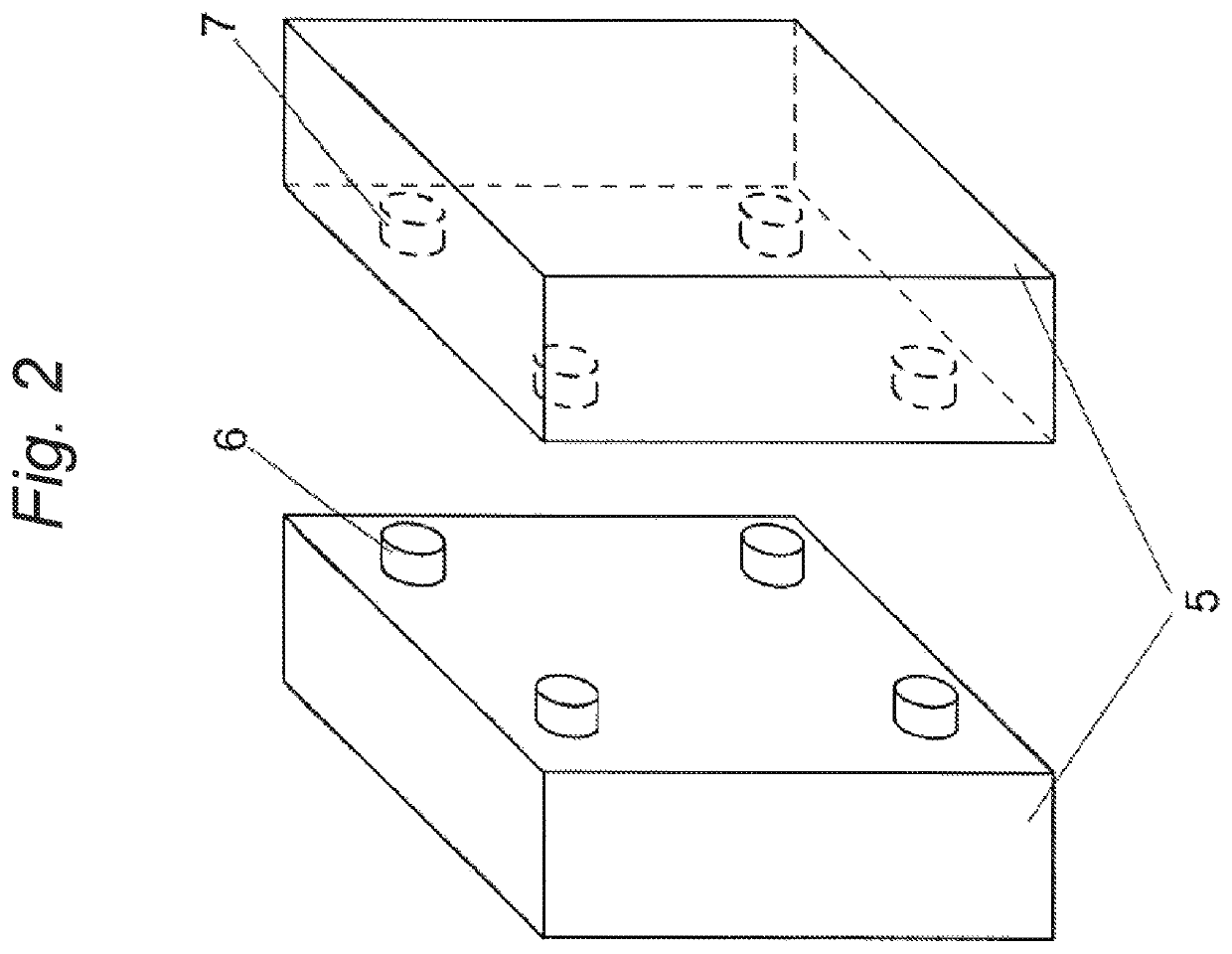
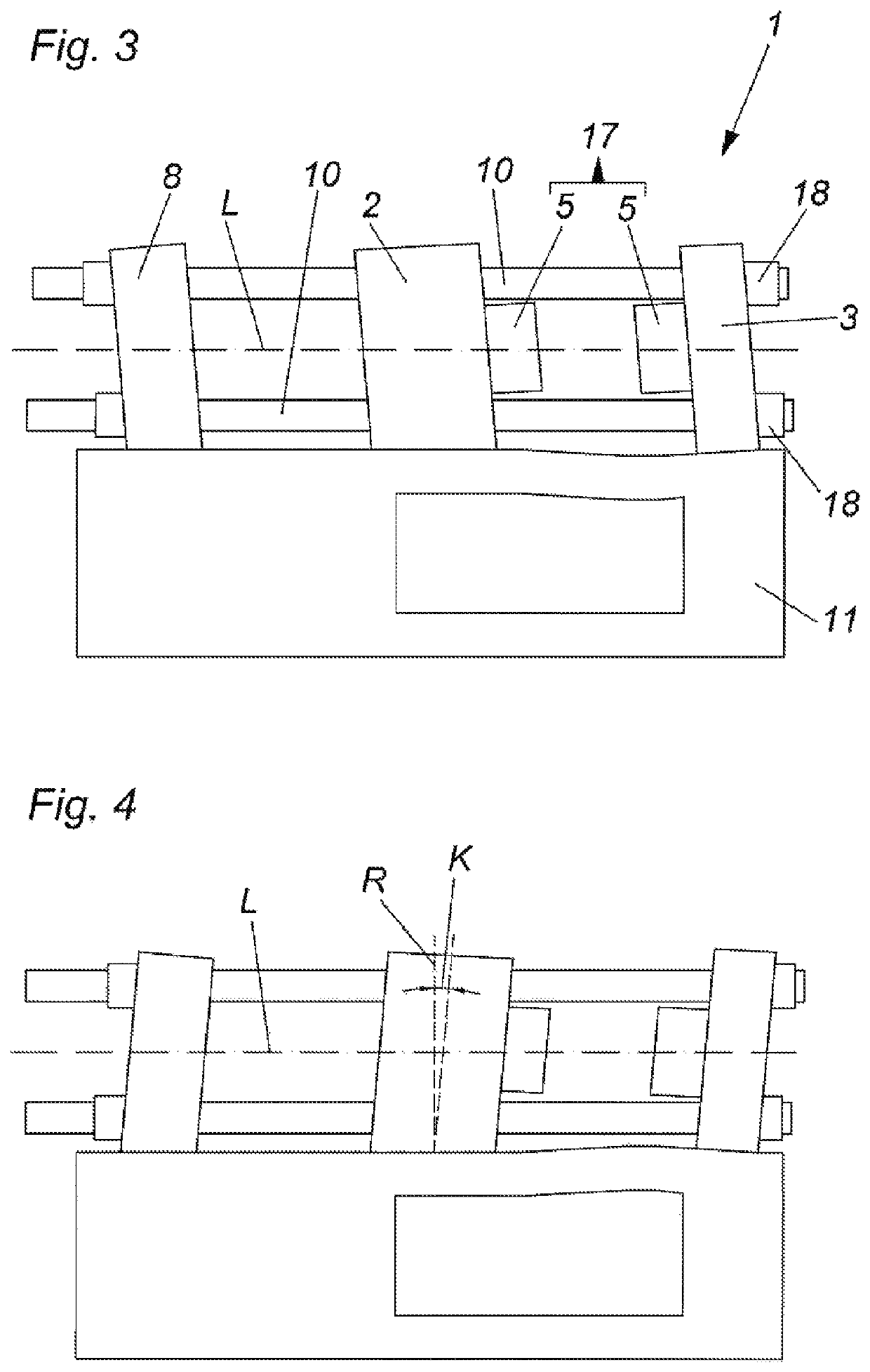
[0044]In general, the FIGS. 1 and 2 correspond to the first variant of the invention and the FIGS. 3 to 6 correspond to the second variant of the present invention. Of course, hybrid forms are possible too.

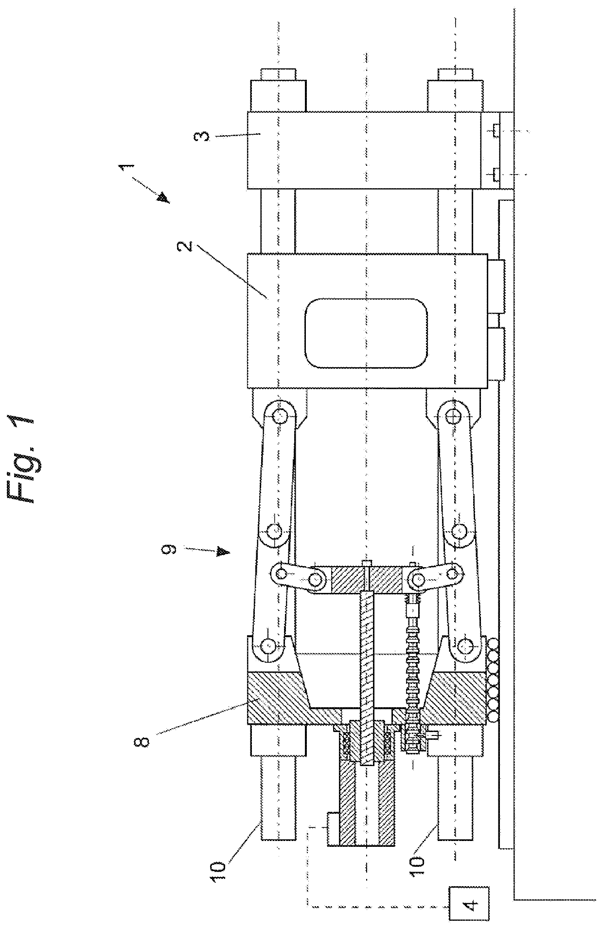
[0045]FIG. 1 shows a molding machine 1 which is here formed as a three-platen injection molding machine comprising a movable mold mounting plate 2, a stationary mold mounting plate 3, a front plate 8 and guiding tie bars 10. A toggle lever mechanism 9 arranged between the front plate 8 and the movable mold mounting plate 2 is here provided as a combined drive and closing force mechanism. This toggle lever mechanism 9 is controlled or regulated by a controlling or regulating device 4 for driving the movable mold mounting plate 2. Measurement values which are representative for the movement of the movable mold mounting plate 2 (e. g. position and / or velocity and / or acceleration of the movable mold mounting plate 2 or of a part of the toggle lever mechanism 9, e. g. a crosshead) can ...


PUM

PropertyMeasurementUnit
distanceaaaaaaaaaa
relative angleaaaaaaaaaa
forcesaaaaaaaaaa

Abstract

A method for moving a movable mold mounting plate of a molding machine, wherein the movable mold mounting plate is movable relative to a stationary mold mounting plate and the mold mounting plates are kinematically connected to each other, wherein molding tool parts arranged on the mold mounting plates are brought into abutment to each other in a closed state and wherein the movable mold mounting plate is moved by a drive mechanism and/or the stationary mold mounting plate is moved by an injection device such that, when reaching a predeterminable distance of the mold mounting plates relative to each other, a parameter representing a tilting movement of the mold mounting plates relative to each other is less than or equal to a presettable value.

Description

BACKGROUND OF THE INVENTION1. Field of the Invention[0001]The present invention concerns (according to a first variant) a method for moving a movable mold mounting plate of a molding machine and a molding machine.2. Description of the Related Art[0002]In the case of a generic molding machine, in particular an injection molding machine for the production of plastic parts made of plastic melt, the movable mold mounting plate and the stationary mold mounting plate are kinematically connected to each other, for example by means of guiding tie bars (in the case of so-called three-platen machines), by means of tension tie bars (in the case of so-called two-platen machines) or by means of a machine frame which transmits closing forces (in the case of so-called tie bar-less machines). When moving the movable mold mounting plate, thus, a tilting of the mold mounting plates to each other occurs by the forces generated when accelerating or braking. The tilting is primarily caused by a tilting ...

Claims


Application Information

Patent Timeline
Patent Type & Authority Patents(United States)
IPC IPC(8): B29C45/80B29C45/66B29C45/76B29C45/64B29C45/17
CPCB29C45/80B29C45/64B29C45/661B29C45/76B29C45/7653B29C2045/1788B29C2945/76093B29C2945/76227B29C2945/76387B29C2945/76578B29C2945/76581B29C2945/76595B29C2945/76705B29C2945/76866B29C45/561B29C45/67
Inventor KILIAN, FRIEDRICH JOHANNPERNKOPF, FRIEDRICHEPPICH, STEPHAN
Owner ENGEL AUSTRIA
Why Eureka
Try Eureka