Variable Capacity Multiple Circuit Air Conditioning System

a multi-circuit air conditioner and variable capacity technology, applied in adaptive control, lighting and heating apparatus, instruments, etc., can solve the problems of a step increase in the control of capacity, not a desired continuous variable increase, and the cost of adding a separate refrigerant circuit with its attendant components

Inactive Publication Date: 2008-12-18
CARRIER CORP
View PDF23 Cites 50 Cited by
  • Summary
  • Abstract
  • Description
  • Claims
  • Application Information

AI Technical Summary

Problems solved by technology

However, it is expensive to add a separate refrigerant circuit with its attendant components to provide the desired contingency capacity.
Additionally, control of capacity is provide

Method used


Image

  • Variable Capacity Multiple Circuit Air Conditioning System
  • Variable Capacity Multiple Circuit Air Conditioning System
  • Variable Capacity Multiple Circuit Air Conditioning System

Examples


Embodiment Construction

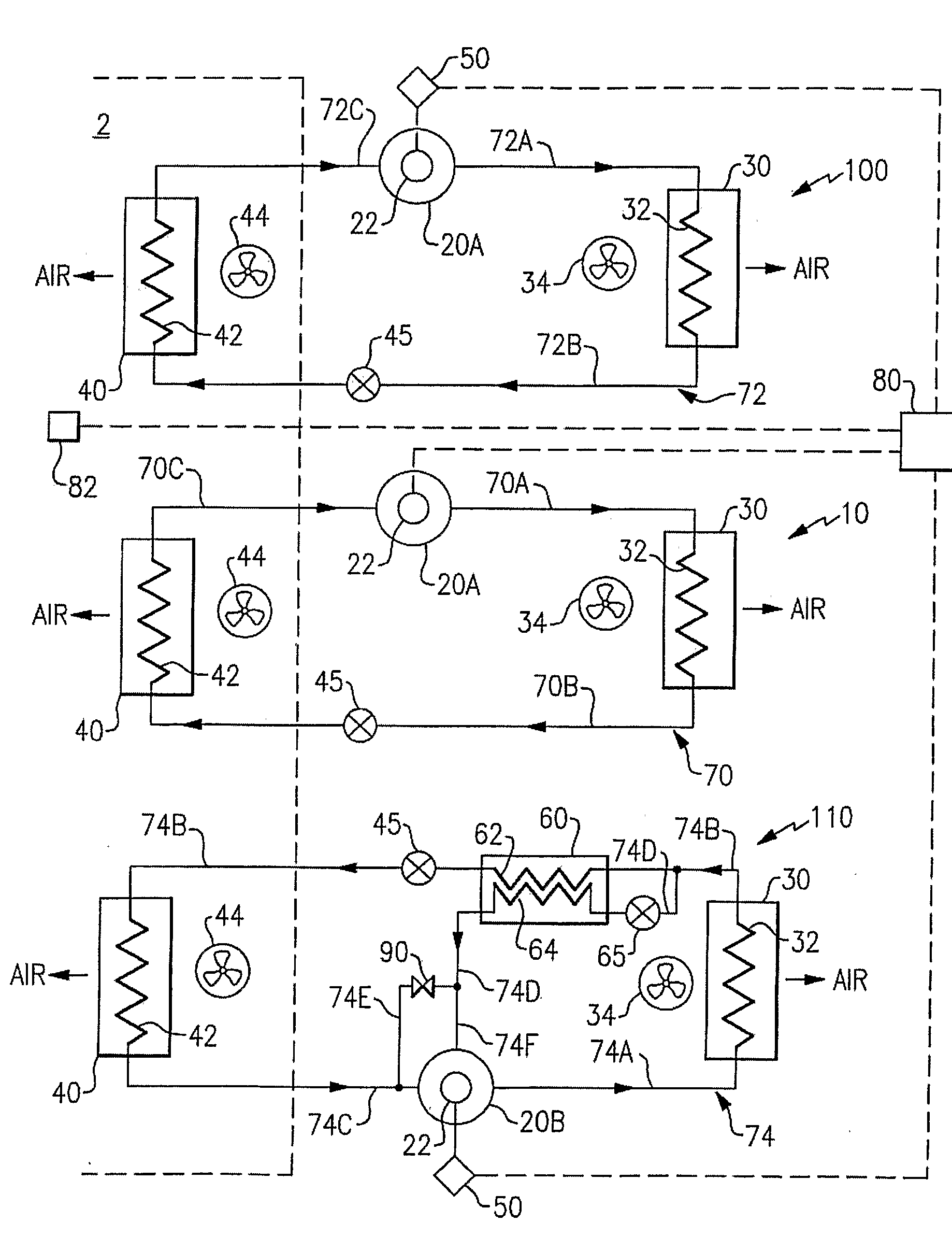
[0015]The refrigerant vapor compression system of the invention, as in the exemplary embodiment in FIG. 1, includes three separate refrigerant circuits 10, 100 and 110, each of which operates independently of the other refrigerant circuits under the direction of a system controller 80 for conditioning air within a climate-controlled space 2. In the depicted embodiment, the refrigerant circuit 10 is a non-economized, air conditioning refrigerant circuit incorporating a fixed capacity compressor, the refrigerant circuit 100 is a non-economized, air conditioning refrigerant circuit incorporating a variable capacity compressor, and the refrigerant circuit 110 is an economized, air conditioning refrigerant circuit incorporating a variable capacity compressor. Although the refrigerant vapor compression system of the invention will be described herein with respect to an air conditioning cycle for cooling air, and generally dehumidifying air, it is to be understood that the refrigerant vapo...


PUM


Abstract

A refrigerant vapor compression system for conditioning air within a climate controlled space has multiple refrigerant circuits including at least one refrigerant circuit having a fixed capacity and at least one refrigerant circuit having a variable capacity. Each refrigerant circuit includes a compressor, a condenser, an expansion device and an evaporator connected in refrigerant circulation flow communication. The compressor associated with each fixed capacity refrigerant circuit is a fixed speed compressor and the compressor associated with each variable capacity refrigerant circuit is a variable speed compressor. A controller is provided for controlling the speed of the variable speed compressor to adjust the refrigeration capacity of the variable capacity refrigerant circuit and thereby adjust the overall capacity of the system to match the cooling demands.

Description

FIELD OF THE INVENTION[0001]This invention relates generally to multi-circuit air conditioning, heat pump or refrigeration systems and, more particularly, to multi-circuit air conditioning, heat pump or refrigeration systems having variable capacity capability.BACKGROUND OF THE INVENTION[0002]Refrigerant vapor compression systems are well known in the art and commonly used for cooling and generally dehumidifying air supplied to a climate controlled comfort zone within an office building, hospital, school, restaurant or other commercial facility. These systems normally constitute a refrigerant circuit including a compressor, a condenser, an expansion device, and an evaporator connected by refrigerant lines in a closed refrigerant circuit in refrigerant flow communication and arranged in accord with known refrigerant vapor compression cycle schematics. An expansion device, commonly an expansion valve, is disposed in the refrigerant circuit upstream, with respect to refrigerant flow, o...

Claims


Application Information

Patent Timeline
IPC IPC(8): F25B1/00F25B7/00F01C1/02G05B15/00
CPCF25B9/008F25B49/022F25B2309/061F25B2400/061F25B2400/13F25B2600/0253F25B2600/0261Y02B30/741Y02B30/70
Inventor LIFSON, ALEXANDERTARAS, MICHAEL F.
Owner CARRIER CORP
Why Eureka
Try Eureka