
Dynamic resource assignment and exit information for emergency responders

a technology for emergency responders and exit information, applied in the field of communication systems, can solve problems such as insufficient perception and information gathered to provide adequate situational awareness, emergency response resources may not be allocated in a manner which maximizes their effectiveness, and emergency response resources may be placed in unacceptably risky situations

Active Publication Date: 2008-12-25
MOTOROLA SOLUTIONS INC
View PDF12 Cites 55 Cited by
  • Summary
  • Abstract
  • Description
  • Claims
  • Application Information

AI Technical Summary

Benefits of technology

[0006]The present invention relates to a method of providing situational awareness at an incident scene. The method can include receiving sensor data from at least one sensor located at the incident scene and receiving positi

Problems solved by technology

Emergency responders at an incident scene often are confronted with a number of issues, one of which is resource management.
Oftentimes, such perceptions and information gathered are insufficient to provide adequate situational awareness.
In consequence, the emergency response resources may not be allocated in a manner which maximizes their effectiveness.
Moreover, some emergency response resources may be placed in unacceptably risky situations.
Another issue that emergency responders confront is the issue of planning for the safe exit of emergency response resources from the incident scene.
For instance, during a structure fire, emergency responders need to be able to find a safe exit from the structure should the fire create unacceptably dangerous conditions within the structure.
Exit signs may be damaged or hidden from view due to smoke or debris, however, and certain exit routes also may be blocked.
Emergency responders therefore may be unaware of the safest exit path and may be exposed to danger longer than is necessary.

Method used


Image

  • Dynamic resource assignment and exit information for emergency responders
  • Dynamic resource assignment and exit information for emergency responders
  • Dynamic resource assignment and exit information for emergency responders

Examples


Embodiment Construction

[0014]While the specification concludes with claims defining features of the invention that are regarded as novel, it is believed that the invention will be better understood from a consideration of the description in conjunction with the drawings. As required, detailed embodiments of the present invention are disclosed herein; however, it is to be understood that the disclosed embodiments are merely exemplary of the invention, which can be embodied in various forms. Therefore, specific structural and functional details disclosed herein are not to be interpreted as limiting, but merely as a basis for the claims and as a representative basis for teaching one skilled in the art to variously employ the present invention in virtually any appropriately detailed structure. Further, the terms and phrases used herein are not intended to be limiting but rather to provide an understandable description of the invention.

[0015]The present invention relates to a method and a system that provides ...


PUM


Abstract

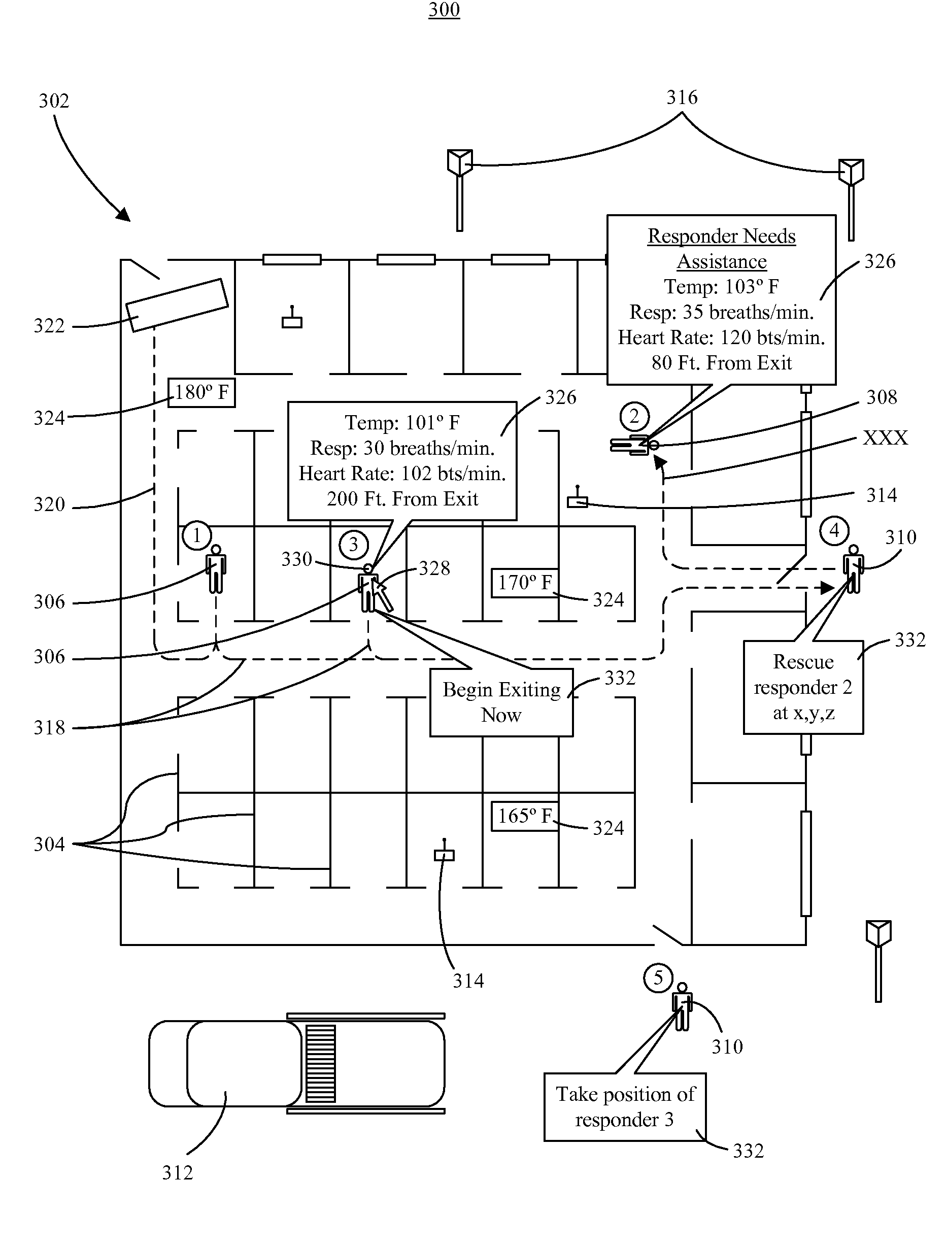
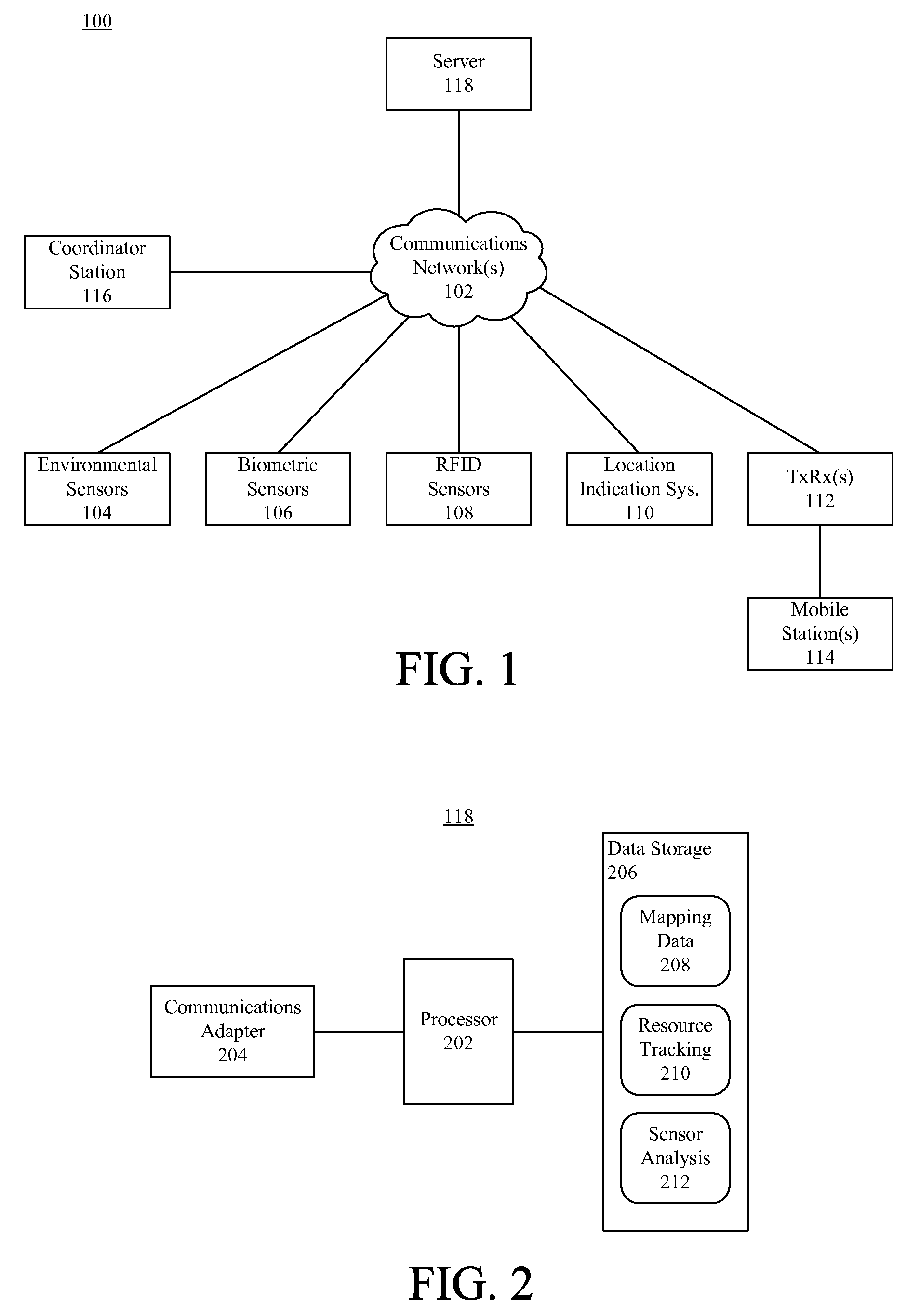
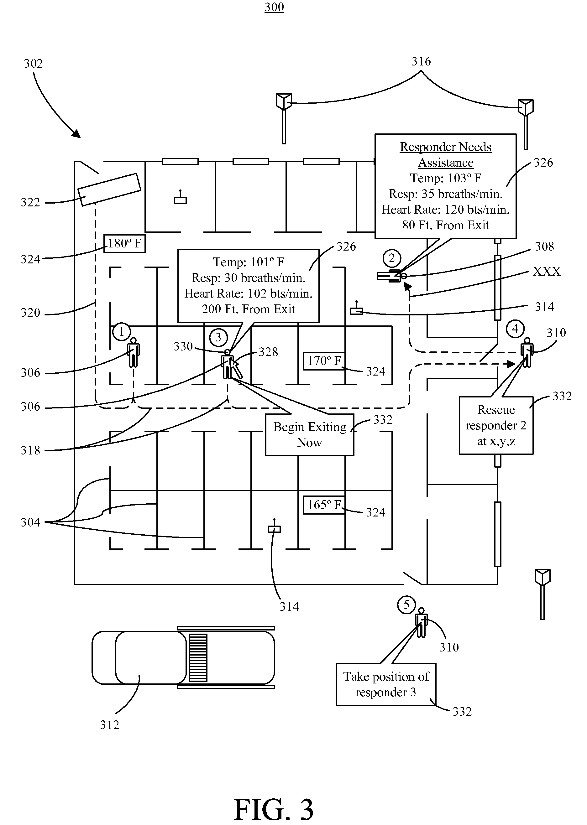
A method of providing situational awareness at an incident scene. Sensor data can be received from at least one sensor (104, 106, 108) located at the incident scene and position data can be received for at least one resource (306, 308, 310, 312). Based on the received data, at least one optimal exit route (318) at the incident scene can be calculated. The present invention also relates to a system (118) that provides situational awareness at an incident scene. The system can include a communications adapter (204) that receives sensor data from at least one sensor located at the incident scene and position data for at least one resource located at the incident scene, and a processor (202) that calculates at least one optimal exit route for the resource to exit a location at the incident scene based on the received sensor data and position data.

Description

BACKGROUND OF THE INVENTION[0001]1. Field of the Invention[0002]The present invention generally relates to communications systems and, more particularly, to emergency response communications systems.[0003]2. Background of the Invention[0004]Emergency responders at an incident scene often are confronted with a number of issues, one of which is resource management. During a structure fire, for example, an emergency response coordinator typically decides how to allocate emergency response resources (e.g. personnel, equipment, etc.) to attack the fire, and then provides instructions to personnel to implement the resource allocations. The decision making process is usually based on situational assessments made by analyzing human sensory perceptions and by gathering information from bystanders. Oftentimes, such perceptions and information gathered are insufficient to provide adequate situational awareness. In consequence, the emergency response resources may not be allocated in a manner w...

Claims


Application Information

Patent Timeline
IPC IPC(8): G08B1/08A62B99/00
CPCA62B3/00A62B99/00G08B7/066G01S5/02A62C99/0081
Inventor PATEL, HEMANG F.METKE, ANTHONY R.
Owner MOTOROLA SOLUTIONS INC
Learn More