Hose nozzle temperature indicator

a technology of temperature indicator and hose nozzle, which is applied in the field of fire fighting, can solve the problems of back drafts subjecting firefighters to life-threatening conditions, poor visibility that accompanies fires, etc., and achieves the effects of increasing safety, reducing back drafts, and improving efficiency

Active Publication Date: 2021-11-02
CORDANI PETER
View PDF15 Cites 0 Cited by
  • Summary
  • Abstract
  • Description
  • Claims
  • Application Information

AI Technical Summary

Benefits of technology

[0010]The display is preferably a digital readout placed on the nozzle and / or coupled to a Heads-Up-Display on the mask of the fireman. Additionally the display can be color coded wherein a blue color indicates a safe temperature, a yellow color indicates a cautionary temperature, and a red color indicates a dangerous temperature. A fireman may use the device to focus on a hot spot using only enough water to drop the temperature to a cautionary or safe level thereby using water more efficiently. A laser positioned next to the sensor on the outlet of the nozzle projects a high intensity visible light toward the area so a firefighter can determine direction with or without fluid flow.
[0011]By incorporating an infrared thermometer-type device into a fire nozzle, an accurate temperature reading of a fire will be displayed as the fireman points the nozzle. Displayed temperatures of fires will allow the firefighter to instantly determine the effectiveness of the application making it a more efficient and effective way to put fires out.
[0012]An objective of the invention is to increase safety while extinguishing fires by providing a nozzle with a built-in infrared thermometer and a laser pointer. The thermometer provides an instantaneous reading of a hot spot and the laser pointing through the smoke and haze to indicate the hot spot.
[0014]Still another objective of the invention is to provide firefighters with situational awareness of a hot spot both by providing a temperature display having a heat index allowing a firefighter to visual depict the intensity of the hot spot.

Problems solved by technology

Water directed to hot spots may immediately turn to steam adding to the poor visibility that accompanies a fire.
Opening of doors that are holding back high heat can further lead to back drafts subjecting the firefighter to a life threatening conditions.

Method used


Image

  • Hose nozzle temperature indicator
  • Hose nozzle temperature indicator

Examples


Embodiment Construction

[0019]Detailed embodiments of the instant invention are disclosed herein, however, it is to be understood that the disclosed embodiments are merely exemplary of the invention, which may be embodied in various forms. Therefore, specific functional and structural details disclosed herein are not to be interpreted as limiting, but merely as a basis for the claims and as a representation basis for teaching one skilled in the art to variously employ the present invention in virtually any appropriately detailed structure.

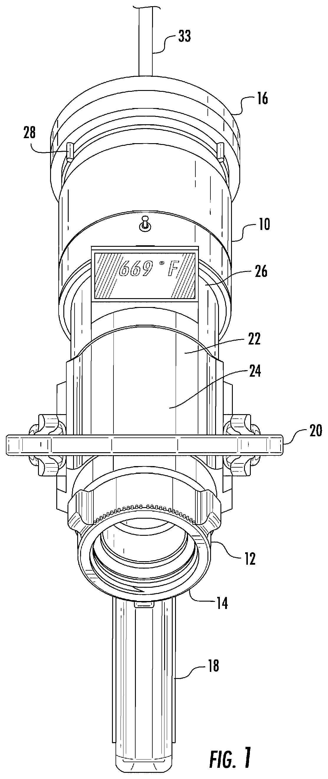
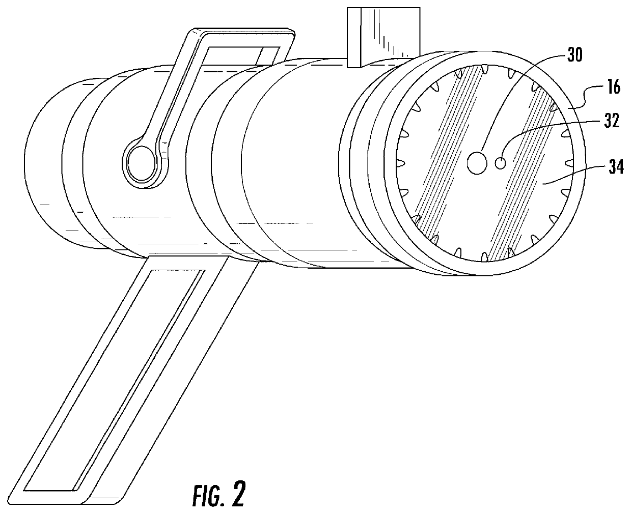
[0020]Now referring to the Figures, the present invention is an improved nozzle 10 formed from a circular shaped body 12 with an inlet 14 and outlet 16. The nozzle includes a pistol grip handle 18 and a pivoting level arm 20 which is pivoted from an open position 22 to a closed position 24 as necessary. A screen 26 is used to display a heat index in either temperature, color, or both.

[0021]The outlet 16 includes an adjustable orifice 28 that can be modified to adjust to t...


PUM


Abstract

An improved nozzle for use with a fire hose having an infra-red temperature sensor that is aligned with an output of the nozzle. The sensor will detect the infrared energy produced by a fire hot spot and provide a visual indication of the energy on a display. The temperature sensor operates a thermometer and is placed in the center of the discharge nozzle allowing water to pass around the sensor. A laser is positioned next to the sensor on the outlet of the nozzle to project a high intensity visible light toward the area that the IR sensor is directed.

Description

PRIORITY APPLICATION[0001]In accordance with 37 C.F.R. § 1.76 a claim of priority is included in an Application Data Sheet filed concurrently herewith. Accordingly, the present invention claims priority to U.S. Provisional Patent Application No. 62 / 721,910 entitled “HOSE NOZZLE TEMPERATURE INDICATOR,” filed Aug. 23, 2018. The contents of the above referenced application is incorporated herein by reference.FIELD OF THE INVENTION[0002]This invention is related to the field of fire fighting and, in particular, to a fire hose nozzle incorporating a temperature indicator.BACKGROUND OF THE INVENTION[0003]Known as a firefighter's “weapon,” a fire hose coupled to a fluid pump and source of water. The fire hose is used to transfer a large volume of water through a nozzle to penetrate a fire causing the fire to be extinguish as the burning material are cooled and unable to reignite.[0004]The fire hose has a proximal end coupled to either a pressurized source of water such as a community suppl...

Claims


Application Information

Patent Timeline
Patent Type & Authority Patents(United States)
IPC IPC(8): A62C99/00G01J5/00B05B12/00G01J5/02G01J5/12G01J5/04G01J5/03
CPCG01J5/0014A62C99/0072B05B12/004G01J5/0066G01J5/025G01J5/0265G01J5/042G01J5/12G01J5/0896A62C31/03G01J5/07
Inventor CORDANI, PETER
Owner CORDANI PETER
Why Eureka
Try Eureka