Electronic apparatus and associated methods

a technology of electronic equipment and associated methods, which is applied in the direction of charging data chargers, batteries, transportation and packaging, etc., can solve the problems of poor match between dipole antennas and the high and slightly capacitive input impedance of typical integrated circuits, and the inconvenient charging via wires

Inactive Publication Date: 2009-01-01
NOKIA CORP
View PDF9 Cites 107 Cited by
  • Summary
  • Abstract
  • Description
  • Claims
  • Application Information

AI Technical Summary

Problems solved by technology

However, charging via a wire may not always be convenient (e.g. requirement for the wire / plug or mains socket to be readily available).
The lack of an onboard power supply means that the device can be quite small: commercially available products exist that can be embedded in a sticker, or under the skin in the case of low frequency RFID tags.
Dipole antennas, however, are a poor match to the high and slightly capacitive input impedance of a typical integrated circuit.
Tags with two orthogonal or nearly-orthogonal antennas, often known as dual-dipole tags, are much less dependent on orientation and polarization of the reader antenna, but are larger and more expensive than single-dipole tags.
Patch antennas are used to provide service in close proximity to metal surfaces, but a structure with good bandwidth is 3-6 mm thick, and the need to provide a ground layer and ground connection increases cost relative to simpler single-layer structures.
Small antennas are usually preferred for convenience, but there is a fundamental limit relating bandwidth, size and efficiency.

Method used


Image

  • Electronic apparatus and associated methods
  • Electronic apparatus and associated methods
  • Electronic apparatus and associated methods

Examples


Embodiment Construction

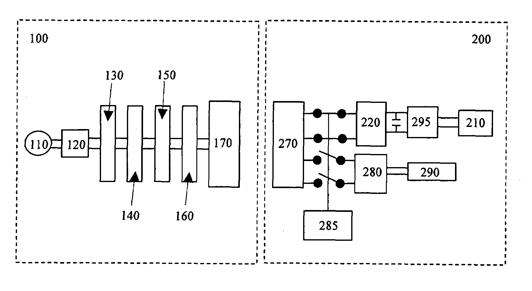
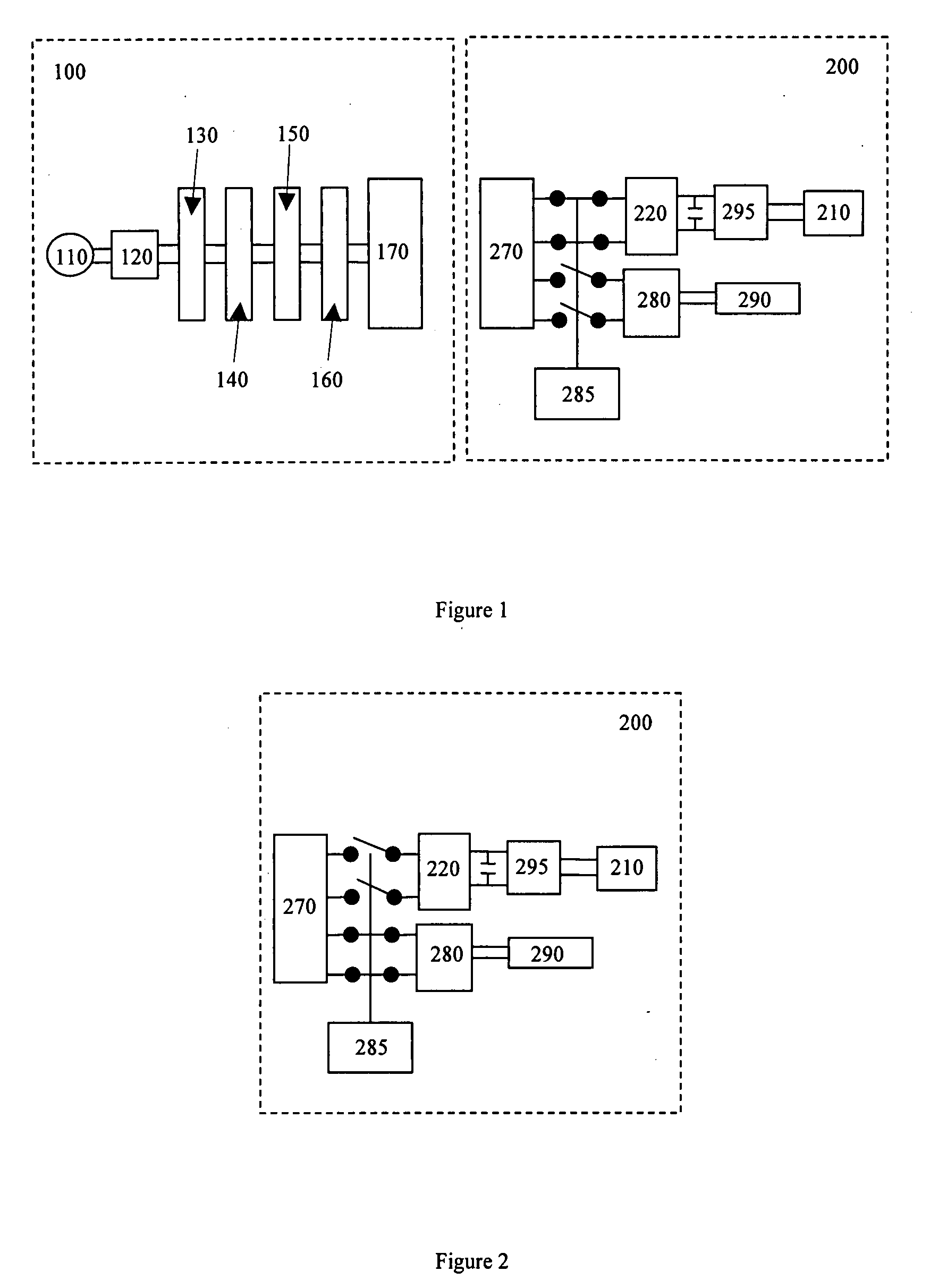
[0062]FIG. 1 shows a charging platform / plate 100 which acts as an apparatus for generating a radiating electromagnetic field to be used to induce current in a device 200 which is associated (e.g. in near proximity) with the plate 100. In this case, the platform 100 is shaped to allow a device 200, which is to be charged, to be conveniently placed on top of the platform 100 to allow charging. It will be appreciated that although the apparatus 100 in this embodiment is a platform, in other embodiments it may have a different structure so long as it provides contactless charging (i.e. does not require the insertion of a plug into the device 200 to provide charging of the device 200). Therefore, in other embodiments, physical contact between the plate 100 and the device 200 may not be required to perform charging i.e. charging may occur if the device 200 is in close proximity (within the region of near field communication) to the plate 100.

[0063]In this case, the plate 100 comprises an ...


PUM


Abstract

An apparatus for receiving electromagnetically induced current, the apparatus comprising an antenna element for receiving electromagnetically induced current in a first apparatus operating mode, and also for near field communication in a second apparatus operating mode, wherein the apparatus comprises circuitry for switching the apparatus from the second apparatus operating mode to the first apparatus operating mode based on near field communication signalling received via the antenna element in the second apparatus operating mode.

Description

TECHNICAL FIELD[0001]The present invention relates to the field of charging of apparatus, particularly for portable electronic devices (e.g. modules for devices or the devices themselves), including but not limited to associated methods (including methods of operation and assembly of associated apparatus), and computer programs.BACKGROUND OF THE INVENTION[0002]Portable electronic devices require a power supply to drive their electronic components. Such devices would often have an in-built rechargeable power supply (e.g. battery / batteries), which may or may not be removable from the device. Most commonly, such power supplies are recharged using a cable to connect the power supply to a recharging source (e.g. mains power supply, or another (e.g. car) battery).[0003]For example, portable electronic devices, including communications devices (such as mobile phones and portable electronic message devices (including e-mail, Short Message Service (SMS) and Multimedia Message Service (MMS) d...

Claims


Application Information

Patent Timeline
Patent Type & Authority Applications(United States)
IPC IPC(8): H02J7/00H01Q7/00
CPCH01Q1/2225H04B5/0081H02J17/00H02J7/025H02J50/20H02J50/80H02J7/00034H02J50/12
Inventor POHJONEN, KATRI HELENA
Owner NOKIA CORP
Why Eureka
Try Eureka